Date
23. July 2004.This
report is a condensed review (with a little humor added) of a MIG robot weld line
used to weld the Ford 500 steel cradles and sub assemblies. The purpose of this
report is to evaluate the robot weld practices being established and examine the
potential robot weld issues that are impacting your robot weld quality and production.
The
manufacturing plant in this article has many weld issues. This plant purchased
Fanuc robots with National Standard E70S-6, 0.045 (1.2 mm) weld wire. For the
welds they of course selected the pulsed process and what they thought was a state
of the art, Lincoln Power Wave F355, pulsed power source. Over 100 robots were
purchased for this plant, none of the robot cells were ordered with automated
TCP controls or joint tracking options The costly Lincoln pulsed power source
used was not necessary adding an additional three to four hundred thousand
dollars unnecessary cost to the robot weld cells. In evaluating specific
robot welding issues at this facility, it's important that the unique robot weld
risks be understood for the welded parts under discussion.
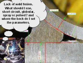
With
robot MIG welds, the primary concerns with common parts 2 to 4 mm is the attainment
of "acceptable and consistent weld fusion", while the concerns for welding
parts less than < 2 mm, is to avoid weld burn through.
 Note:
On steel parts > 2 mm, the weld reality in the auto / truck industry, is one
in three or four welds will end up with lack of weld fusion in some part of the
weld.
Note:
On steel parts > 2 mm, the weld reality in the auto / truck industry, is one
in three or four welds will end up with lack of weld fusion in some part of the
weld.
The Chicago
plant provides many welds on steel parts < 1.8 mm. On these parts the MIG weld
burn through potential is at a high level and part dimensional plus robot TCP
deviations will compound the burn through issues As this plant ramps up for it's
robot weld production, it's unlikely that the part dimensions will improve and
this combined with the lack of automated TCP controls, will ensure that the weld
issues, unless addressed will increase in proportion to the weld production attained.
To minimize the potential robot weld issues that will occur, the plant
needs more focus on the implementation of best weld practices and the requirements
for weld process optimization and process controls.
In
the automotive industry, the selection of inappropriate MIG weld consumables and
inferior weld process modes has for two decades created major weld issues. As
the robot steel parts decrease in thickness < 2 mm, the consequences of poor
weld consumable / process selection really become evident.
In
many auto / truck manufacturing plants, weld consumable selection may have more
to do with a purchasing decision cost reduction decision rather than a logical
weld engineering decision. With the majority of the robot lines installed in the
auto / truck industry during the last five years, the selection of the weld equipment
and consumables typically has had more too do with salesmanship than with practical
weld process considerations.
The following weld data will assist the
plant in establishing best weld practices for the cradle parts < 1.8 mm.
Present
Weld Practices. The Chicago location is utilizing Fanuc robots, E70S-6, 0.045
(1.2 mm) weld wire, and the new Pulsed, Lincoln Power Wave F355 i weld equipment.
The Fanuc robots at this plant do not have automated TCP controls. The weld wire
size selected is not appropriate, for the gage parts and the power source used
is a poor / costly choice which has added at least $300,0000 unnecessary cost
to the cradle robot line.
BEST
WELD PRACTICES. THE IMPORTANCE OF TCP CONTROL .
 Part
dimension and TCP control will always be critical when welding gage applications.
The thinner the gage, the smaller the required welds and the greater the degree
of weld / joint accuracy. TCP control also enables an altered program to be put
back to the original program with minimal deviation of the gun to the work. In
this facility, in the robot cells, there are no means for accurately checking
the robot TCP and you will find programmers constantly making changes to the welds,
none of which have anything in common with the original program. This plant was
typically loosing 20 minutes of robot (lost production from 33 robots)
down timer per-hour due to program weld point adjustments and tip issues.
Part
dimension and TCP control will always be critical when welding gage applications.
The thinner the gage, the smaller the required welds and the greater the degree
of weld / joint accuracy. TCP control also enables an altered program to be put
back to the original program with minimal deviation of the gun to the work. In
this facility, in the robot cells, there are no means for accurately checking
the robot TCP and you will find programmers constantly making changes to the welds,
none of which have anything in common with the original program. This plant was
typically loosing 20 minutes of robot (lost production from 33 robots)
down timer per-hour due to program weld point adjustments and tip issues.
Also on the parts with gaps or inconsistent dimensions, you typically have
to be able to place "oversized welds" to compensate and of course over
sized welds will increase the weld burn through potential, especially on the 1.5
- 2 mm parts. To avoid weld burn through with the larger welds, aggressive weld
weaves are beneficial, the plant made no use of the weaves that were in the
robot program. Unfortunately with weld burn through, the resulting holes will
disrupt the arc and frequently cause the weld wire to end up with excess length
which cause arc strike / contact tip issues.
BEST
WELD PRACTICES. THE GMAW PULSED POWER SOURCE SELECTION.
For
almost two decades, the MIG equipment manufactures have been developing and promoting pulsed MIG equipment for "steel applications". The Lincoln
pulsed equipment purchased for your robot weld lines has undergone years of development
yet still in 2004 provides "poor arc stability" along with arc length
sensitivity. The pulsed arc length sensitivity makes the pulsed mode unsuitable
for most of your high weld speed steel applications. It's ironic that the weld
equipment purchased also has cost 50% more than the available superior, stable,
traditional CV equipment. The pulsed weld equipment purchased will likely cost
three times as much to repair and you will need to keep more spare equipment than
normally would have been required with traditional, more durable CV equipment.
promoting pulsed MIG equipment for "steel applications". The Lincoln
pulsed equipment purchased for your robot weld lines has undergone years of development
yet still in 2004 provides "poor arc stability" along with arc length
sensitivity. The pulsed arc length sensitivity makes the pulsed mode unsuitable
for most of your high weld speed steel applications. It's ironic that the weld
equipment purchased also has cost 50% more than the available superior, stable,
traditional CV equipment. The pulsed weld equipment purchased will likely cost
three times as much to repair and you will need to keep more spare equipment than
normally would have been required with traditional, more durable CV equipment.
When using an
0.045 MIG wire and pulsed welding the cross members and similar seam lap welds,
to attain the desired minimum weld travel rate of 50 ipm, on the 1.6 mm lap welds,
the MIG weld wire has to virtually make contact with the weld surface. This "wire
to work contact" not only causes extensive weld spatter which will impact
the tip life, the weld spatter also gets on to the fixtures causing part assembly
/ fit issues. When establishing the pulsed trim voltage (arc length) with the
high speed pulsed applications, if the pulsed weld voltage (arc length) is set
to a none weld spatter condition, the weld transfer and instability at 50 ipm
will cause "skip" welds (missed welds / weld blobs).
 Typically
with this present day power source technology, when pulsed welding we need a sufficient
arc length to enable the pulsed MIG weld drops to form and transfer without making
a short circuit contact with the work and wire tip. With the Lincoln equipment
, the desired minimum arc length required for optimum pulsed weld transfers is
detrimental when pulsed welding thin gage parts using 0.045 wire at "high
weld speeds". The thin gage parts limit the allowed pulsed wire feed rate
which limits the pulsed frequency. The low pulsed frequency with the large wire
diameters and a weld which for 50% of its time is at a background current of less
than 100 amps is resulting in an unstable weld transfer unsuited to high weld
speeds on the cradle welds.
Typically
with this present day power source technology, when pulsed welding we need a sufficient
arc length to enable the pulsed MIG weld drops to form and transfer without making
a short circuit contact with the work and wire tip. With the Lincoln equipment
, the desired minimum arc length required for optimum pulsed weld transfers is
detrimental when pulsed welding thin gage parts using 0.045 wire at "high
weld speeds". The thin gage parts limit the allowed pulsed wire feed rate
which limits the pulsed frequency. The low pulsed frequency with the large wire
diameters and a weld which for 50% of its time is at a background current of less
than 100 amps is resulting in an unstable weld transfer unsuited to high weld
speeds on the cradle welds.
Note: It's a logical practice to check out
weld equipment before you purchase it.
The
robot, high speed skip weld issues you have at the plant are the same pulsed weld
issues every wheel manufacturer and torque converter manufacture has had to deal
with through for the last decade.
Another
ironic fact is when you use the Lincoln pulsed equipment in the traditional spray
transfer modes which provides improved arc stability is the weld decision maker
may not be aware that the slope influenced performance of the traditional spray
mode from the pulsed MIG equipment is typically inferior to the lower cost traditional
CV equipment.
To
attain high speed welds with weld transfer stability, I recommend the pulsed mode
should be replaced with the more stable, less arc length sensitive "spray
transfer mode". While the spray mode runs hotter than the pulsed this is
not a concern for the welds on the parts > 2mm as the the weld heat can be
reduced through the faster weld speeds and the selection of a smaller MIG wire
diameter such as an 0.040 or 0.035 wire.
Note:
Remember this is 2004 pulsed equipment and although I saw the pulsed issues on
numerous occasions and documented them at this site, poor performing pulsed equipment
was something companies like MIller. ESAB and Lincoln did not discuss in public,
after all you may not have bought the pulsed equipment if they told you the truth.
Note:" There is not be the same electronic and weld transfer concerns
with most of the pulsed equipment sold > 2006.
July
30-04. E Mail to Ed,
Ed:
Your description of arc sensitivity with high speed pulsed welds is exactly what
I am experiencing with our robots and the new Miller Accu-Pulse process / Auto
Axcess. Our new auto bumpers are thin gage, 1/16 1.6mm HSLA and martensite concerns.
I tried to weld above 40 IPM with the Accu-Pulse and could not do to weld skipping
and arc instability. We went to an .035 1 mm wire and could not get the travel
speeds. We changed to .045 1.2 and had to run the pulsed arc with the arc length
buried in the part, this resulted in extensive weld spatter also the part could
not handle the pulsed weld heat and we would have holes all over the place. With
the disappointing pulsed weld results we now use high end short circuit CV with
the 045 wires and are attaining 40IPM travel rates. I have no spatter on the part
and have no arc stability problems with the short circuit. I hate to admit it
but this is is another pulsed failure in my book. I could get these short circuit
results CV power source for half the costs..
Regards G S.
 WELD
BEST PRACTICES. WIRE DIAMETER SELECTION. As I write this report one of your
competitors is utilizing 0.052 1.4 mm weld wires on Ford frames 2 to 4 mm. This
company is also using the same pulsed Lincoln equipment as you. They also went
through
WELD
BEST PRACTICES. WIRE DIAMETER SELECTION. As I write this report one of your
competitors is utilizing 0.052 1.4 mm weld wires on Ford frames 2 to 4 mm. This
company is also using the same pulsed Lincoln equipment as you. They also went
through  the
consequences of the pulsed arc instability, and they were unable to use spray
with the large weld wires. The programmers at the plant unknowingly dialed in
lower "globular parameters" which are causing all types of production
and quality problems, (see frame plant report at this site).The globular transfer
caused over 80% weld rework.
the
consequences of the pulsed arc instability, and they were unable to use spray
with the large weld wires. The programmers at the plant unknowingly dialed in
lower "globular parameters" which are causing all types of production
and quality problems, (see frame plant report at this site).The globular transfer
caused over 80% weld rework.
The choice of an 0.045 wire for short circuit
and spray welds that will be made on parts less than 1.8 mm is also an inappropriate
choice.
The Chicago
facility and the cradle welds will benefit from stable spray transfer and a smaller
wire diameter than 0.045 (1.2mm) Lets take a moment to look at the MIG weld current
compatibility with standard gage thickness used at the cradle facility.
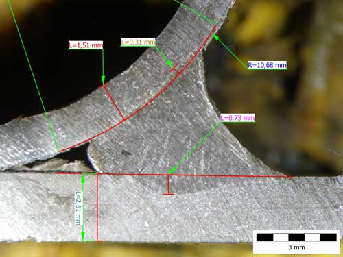
[]
With robot, single pass "butt" welds on 1.6 mm cradle parts, we typically
would be in the short circuit mode, welding at 170 - 200 amps. Lap welds do allow
higher weld current, however the butt weld data shows the part compatibility with
the weld current utilized.
[] With the cradle 1.8 mm parts, the butt weld
current would be increased to approx. 220 amps. For any application that uses
a weld current over 200 amps we would want to use the high deposition, stable
spray transfer mode. Butt welds on 2 mm parts could be robot welded using 240
- 260 amps.
An
0.045 wire requires a minimum of 250 - 260 amps to attain stable spray transfer.
As many of the welds you produce require less than 260 amps it makes no sense
to use a consumable that will simply cause weld burn through on many of your parts.
The bottom line it's imperative the plant uses an 0.035 or 0.040 wire. The common
0.035 wire will go into spray around 200 amps.
The
negative attribute of the 0.035 wire is
[a] wire feed ability,
[b]
a smaller weld width influenced by the smaller plasma.
The
wire feed ability issues can be addressed from a maintenance perspective. Also
keep in mind that the rarely used 0.040 wire is most suited to your applications
and this wire has less potential feed issues than the 0.035 wire. From my perspective
the 0.040 wire should be the wire of choice for the auto parts industry for all
applications
under 4 mm.
BEST
PRACTICES AND WELD WIRE COSTS.
 I
can understand why third world countries get uptight about weld consumable costs,
however in many North American auto plants weld engineers should not have to worry
about the $1 a pound MIG wire costs. As bigger wires cost less, in many auto plants
purchasing managers rather than engineers may decide on the wire diameter selected.
A typical auto cradle may today use approx. 1 to 2 lbs of weld wire per cradle.
So the purchasing manager can save 20 to 30 cents a cradle by recommending an
0.045 or 0.052 wire instead of the 0.040 or 0.035 wires. In this case changing
the weld wire to a smaller wire will dramatically improve both the weld productivity
and quality, but hey why worry about a daily, lousy robot production of 60% with
30 % daily weld rework, when the purchasing manager can save 20 cents a part.
I
can understand why third world countries get uptight about weld consumable costs,
however in many North American auto plants weld engineers should not have to worry
about the $1 a pound MIG wire costs. As bigger wires cost less, in many auto plants
purchasing managers rather than engineers may decide on the wire diameter selected.
A typical auto cradle may today use approx. 1 to 2 lbs of weld wire per cradle.
So the purchasing manager can save 20 to 30 cents a cradle by recommending an
0.045 or 0.052 wire instead of the 0.040 or 0.035 wires. In this case changing
the weld wire to a smaller wire will dramatically improve both the weld productivity
and quality, but hey why worry about a daily, lousy robot production of 60% with
30 % daily weld rework, when the purchasing manager can save 20 cents a part.
YOU
ARE NOT LIKELY TO USE WELD WEAVES IF YOU DON'T UNDERSTAND THE WELD BENEFITS FROM
WELD WEAVES:
THIN PARTS AND WELD WEAVES.
The plant was not using weaves in any of the robot cells. The plant should consider
when required, the use of weld weaves for specific problem welds. The weld weaves
should comprise of amplitude that creates a narrow, high speed oscillation in
the weld center. This weld weave oscillation will not impact the potential weld
speeds, it will however cause the fast freeze thin welds to thin out and provide
slightly wider weld coverage.
Three
important weld benefits are attained from the weld weaves on gage parts;
[1]
Reduce weld burn through potential.
[2] Helps compensate for gaps.
[3]
Helps compensate for part dimensional deviations.
If you are reading
this today a few years will have passed since it was written. Do you see any similar
issues in your plants? Hopefully this tongue in cheek weld article will assist
some UN-blinkered auto / truck manufacturers to give a little more consideration
to weld process and equipment requirements. If you want to spend less time trying
to put out the weld shop fires that daily spread through too many weld shops,
managers, engineers and technicians and any weld decision maker involved, all
need to walk the same path to weld process optimization, in other words for god's
sake get some process control training.
INABILITY
TO DETERMINE QUALITY WELDS. I would also like to comment that when evaluating
your NAMS weld cross sections, that most of the welds your personnel are rejecting
are in reality perfectly acceptable. I suggest you provide training so your weld
quality personnel understand the real meaning of weld quality. Regards Ed Craig.


 INFLATED
WELD PROCESS CONFIDENCE. At many North American auto / truck parts plants,
when the robot welded parts are >2 mm, thanks to good part fit and the low
weld burn through risk, and the simple fact that few of the welds will have an
internal weld evaluation, you will often find that the managers, engineers and
technicians have an inflated weld process confidence with
typically minimal weld process expertise. Along with the unwarranted weld
confidence it's not difficult in these plants to find managers and engineers who
do not believe in process ownership. Also you won't have to look far to find young
technicians with 24 months expertise and swollen egos and attitudes and these
rookies will have decided they no longer need to further their very limited weld
process education. They don't need process expertise yet the majority would have
a difficult time with this fundamental process control
INFLATED
WELD PROCESS CONFIDENCE. At many North American auto / truck parts plants,
when the robot welded parts are >2 mm, thanks to good part fit and the low
weld burn through risk, and the simple fact that few of the welds will have an
internal weld evaluation, you will often find that the managers, engineers and
technicians have an inflated weld process confidence with
typically minimal weld process expertise. Along with the unwarranted weld
confidence it's not difficult in these plants to find managers and engineers who
do not believe in process ownership. Also you won't have to look far to find young
technicians with 24 months expertise and swollen egos and attitudes and these
rookies will have decided they no longer need to further their very limited weld
process education. They don't need process expertise yet the majority would have
a difficult time with this fundamental process control