Tungsten
Inert Gas Welding - Tig Welding Tips
For
the world's most effective
TIG weld process, click on TIP TIG
Email. Question.
Hy
Ed. Would you please provide some guidelines and general data for establishing
automated TIG welding parameters
Answer. First please note that those who utilize the regular GTAW process for manual or automated welds should consider the TiP TiG process which I bought to North America around 2008. When GTAW filler metal is required, in contrast to regular TIG, Hot Wire TIG or Cold Wire TIG, the TiP Tig process when filler metal is required is easier to use, will provide better weld quality, better metallurgical results and welds at an approx. 25% of the typical GTAW weld labor costs.
When automated
TIG welding, an important first requirement is determine the
approximate weld current required for the specific welds. Once the approximate
weld current range is determined, then select the correct tungsten electrode size.
The following enables the correct size tungsten electrode.
|
TUNGSTEN SIZE AND APPROX. WELD CURRENT
RANGE FOR REGULAR TIG, DCEN.
Tungsten
Ceriated
Lanthanaum
0.020
(0.5mm)
0.040
(1.0mm)
|
Tungsten
DCEN Amp
Range
5 - 20A
15 - 70A
|
BEST
EQUIPMENT FOR ALUMINUM TIG WELDS IS A POWER SOURCE WITH AN EN-EP WAVE BALANCE CONTROL.
WITH THE BALANCE CONTROL, THERE IS NO NEED FOR AC CURRENT / TUNGSTEN CONCERNS.
WITH
ALUMINUM WELDS & BALANCE CONTROL, SIMPLY USE A LANTHANUM OR CERIATED TUNGSTEN AND USE THE SIMILAR CURRENT
AS USED WITH DCEN,
|
0.062
(1.6mm)
|
70-140A
|
3/32
(2.4mm)
|
130-
210A
|
1/8
(3.2mm)
|
200-
310A
|
5/32
(4mm)
|
250
- 500A
|
Try
and ensure with
the TIG tungsten selected, that the weld current most frequently
used is not > 80% of the recommended weld amp range for the tungsten.
|
TIG Weld Equipment Tip.
Anyone who
has worked with TIG Welders and automated and orbital TIG systems, knows
the process plasma is very arc length sensitive and therefore the TIG arc continuity and weld quality is highly dependent on retaining the shape and quality of
the tungsten welding tips.
As TIG are starts can greatly impact the tungsten tip wear, TIG weld start data can be critical especially with automated TIG welding applications.
Tungsten life is improved with a times Start Ramp Up from a low current to the operating current.
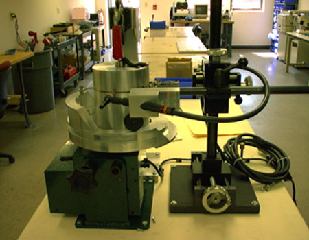
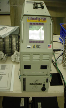
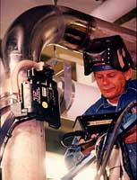
The Cobra TIG 150A power source is
shown below. From my perspective, this is one of the best, economical, small pulsed TIG power sources
designed for "orbital tube welds". No useless bells and whistles, just logical, practical weld process control features.
This equipment delivers consistent, controlled weld results and the company that
provides the equipment provides excellent equipment product support. The Cobra
TIG power source is available from MK products California.
|
TIG
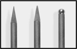
TUNGSTEN ELECTRODE PROFILE TIP:
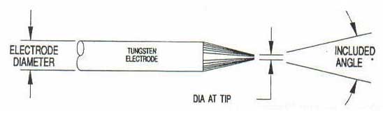
Best Included angle for most welds > 50 amps,
45 - 50 degrees included angle with a small flat surface.
AUTOMATED TUNGSTEN LONGEVITY TIP:
For
automated TIG welds with AVC Controls, or an application that has good tungsten to work Height Control,
with the use of correct tungsten type, size and parameters, both a tungsten with a point
and a tungsten with a small flat spot with a 20 to 25 degree (40 - 50 included angle, should be able
to get the tungsten through at least an arc on weld duty cycle time of 6 to 8 hours without
a tungsten regrind or a tungsten change.
|
PULSED
TIG WELDING DATA:
Weld Tip: THE NEED FOR PULSED TIG PARAMETERS:
This is an overused option on many none alum TIG applications. Use
pulsed as a LOWER ENERGY weld solution to HEAT related weld problems that occur with the TIG process. The most consistent weld quality is typically attained in a TIG weld arc not using a pulse.
|
Pulsed TIG is not required with 99% of weld applications
when using
the superior
TiP TIG process
GENERAL
TIG WELDING DATA:
For steel and alloy steel applications, avoid radiation concerns with Thoriated
tungsten, and use 1.5% Lanthium or Ceriated Tungstens.
WITH AUTOMATED WELDS, FOR CONSISTENT
ARC STARTS AND TO ENSURE CONSISTENT WELD QUALITY, THE GTAW (TIG) "ARC LENGTH" IS CRITICAL, IN CONTRAST WITH TiP TiG, IT'S LESS CRITICAL:
DESIRED APPROX. ARC LENGTH (AL). The arc gap between the Tungsten and weld surface.
AL with applications that TIG weld at 15 to 30 amps = 0.025 - 033
AL with applications that TIG weld at 30 to 50 amps = 0.030 - 038
AL with applications that TIG weld at 50 to 70 amps = 0.040
AL with applications that TIG weld at 70 to 150 amps = 0.070 - 0.080
AL with applications that TIG weld > 150 amps = 0.125 - 0.165
TIG WELDING SPEEDS - TIG WELD, TECHNIQUES.
 Most automated TIG welds are carried out with very low weld deposition rates of 0.5 - 2 lbs/hr therefore low weld speeds are typically Most automated TIG welds are carried out with very low weld deposition rates of 0.5 - 2 lbs/hr therefore low weld speeds are typically
Note: With TiP TiG expect a 200 to 500% increase in automated and manual weld speeds.
If
you don't know the traditional TIG weld speed, start at in the weld speed range of 2 - 5 ipm. With TIG, use a fore- hand (push) position for the tungsten as this helps break
up the metal oxides in front of the welds. This enables cleaner welds and arc continuity..
RAMPING
DOWN THE CURRENT AT THE WELD END ASSISTS IN REDUCING
WELD CRATER CRACKS AND
ADDS TO THE TUNGSTEN LIFE.
For TIG weld Crater Fill, use both ramp down current, and back stepping to minimize cracks.
ORBITAL TIG WELDING AND REQUIRED WELD SCHEDULES.
An Orbital
TIG weld procedure typically requires a minimum of four -six weld parameter schedules per weld
This is necessary for the weld start / ends and to compensate
for the increased weld heat that occurs as the TIG weld travels 360 degrees around
the tubes.
For example an orbital weld schedule may drop the weld current by 10 - 20% between
each of the 4 schedules as the weld heat builds up during the TIG torch rotation.
Note: The smaller and thinner the tube welds, the faster the TIG weld heat build
up.
Typical Orbital Weld Procedure.
[1] Start: Provide
ramp up weld start 20 amps that leads into weld schedule 1.
[2]
Schedule 1. Travel from
12 to 3 o'clock with 60 amps into schedule 2.
[3] Schedule 2. the torch travels 3 to 6 o'clock
at 55 amps into schedule 3.
[4]
Schedule 3. The TIG torch travels between
6 to 9 o'clock at 50 amps into schedule 4.
[5] Schedule 4. The torch travels between
9 to 12 o'clock at 48 amps.
[6]
Then apply the weld crater fil,l and finish data that will
ramp the current down as low as 1 amp.
For
great orbital tube or pipe auto TIG equipment check out either MK and AMI power sources, California.
For manual, conventional TIG applications my choice is typically Miller power source followed by ESAB.
Note:
FRONIUS
has some interesting TIG equipment but tends to be overpriced with too many unecessary bells and whistles for the weld shop.
TIG Aluminum. Tip
Question:
Ed. We are TIG welding Aluminum parts. When we use the AC TIG mode, we can set
the AC balance control towards Electrode Positive or Negative, and yes are welders
all use different settings for the same parts. Each welder would swear that their balance setting is the best.
Is there any logic we should apply as to the optimum setting.
Thanks for your web site.
Kyle
Answer.
With AC welding we get a weld arc influenced by both EP and EN. In the EP part of the arc cycle, the majority
of the electrons will flow to the tungsten tip from the work surface, while the larger Positive gas molecules
hit the aluminum Negative surface, breaking up the alum oxide skin. Unfortunately EP sends to
many electrons and energy to the tungsten tip, and the resulting heat build will melt the tip end. To
avoid the tungsten tip damage, with all TIG welds on most steel applications we use EN (electrode negative). With EN
the electrons are driven away from the tungsten to the work. With AC aluminum welds
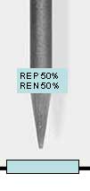
and a balance control, it's beneficial to use an arc with a little amount of EP
added for the oxide removal. With the balance control set that start balance control at 80% EN and 20% EP. Check the weld
cleaning etch if its too wide decrease EP, not enough increase EP. For a tighter
narrower TIG plasma increase EN, for the opposite decrease EN.
 Note You can with the balanced polarity settings above, use conventional tungsten and avoid the ball that occurs with pure tungsten and AC.. Note You can with the balanced polarity settings above, use conventional tungsten and avoid the ball that occurs with pure tungsten and AC..
View more about TIG Aluminum.
|
Tungsten is very oxide sensitive. To eliminate tungsten oxidation, inert argon is utilized for most TIG welds. When the argon purity is a concern, the use of liquid argon in small bulk cylinders will provide the highest gas purity. Gas contamination
is common in HIGH pressure cylinders that have not been purged before use,
or possibly the cylinders have been previously used for MIG gas mixes that contain
reactive gases such as O2 or CO2.
For most common TIG welds, Use a flow rate of 15 to 20
cuft/hr, start out at 15 cuft/hr. For high speed or deeper TIG penetration welds,
flow rates will typically be increased between 20 and 40 cuft/hr.
WHEN THE TIG WELD ENERGY NEEDS TO BE INCREASED;
When
requiring higher energy TIG welds, before considering costly argon - helium or argon
- hydrogen gas mixes, for any TIG application start out on a piece of scrap with
straight argon and ensure the weld current required is compatible
with the tungsten size utilized. It's a fundamental fact, that for all weld applications
and all alloys that will require less than 200 amps, that straight argon should be the
logical choice. Its also a fact that if you need high energy TIG weld you should
be using the TIP TIG process which rarely requires helium or hydrogen gases.
Note: I
believe all TIG applications benefit from the use a gas lens. The use of gas lens
also allows for greater tungsten extension which is beneficial on groove joints and joints with
tight restriction.
 WELD
SPEEDS - WELD ENERGY AND AUTOMATED TIG APPLICATIONS: WELD
SPEEDS - WELD ENERGY AND AUTOMATED TIG APPLICATIONS:
If
you using high currenti , to further
increase weld energy or speeds, (automated applications only) with steel applications, try
a 60 - 70% helium balance argon mix. With austentitic and some nickel
welds, the addition of hydrogen in the range of 5 - 30% may provide faster
and cleaner welds. With most austenitic 300 series applications, nitrogen may
be used for the weld BACK UP / PURGE gas. Remember that when TIG welding, with approx. 90%
of TIG applications, you will get ther job done with straight argon.
Note:
Ed helped write the AWS MIG Gas Specifications and developed three of the most common MIG gas mixes used in North America. Visit
the MIG gas section if you want to get the salesmanship out of gas selection.
Consider
argon with 5 - 30% hydrogen if you want more weld wetting or faster faster weld
speeds. Remember an increase in weld speed may have little value if the weld cycle
time is measured in seconds. The hydrogen addition to argon can increase arc stability
on specific, very thin low amp applications < 10 amps. When welding specific
alloy steels with hydrogen gas, be beware of the potential for hydrogen embrittlement.
Hydrogen can also decrease the potential life of the tungsten, depending on the
hydrogen content and tungsten type.
Note:
TIP TIG Welding enables the fastest possible TIG weld speeds and typically requires only
argon:
TIG GAS PRE FLOW AND POST FLOW.
Starting the TIG arc and finishing the arc without sufficient
pre - post gas flow will cause instant damage to the tungsten. Using a controlled
pre- and post flow control is critical. If you wish to retain the integrity of the tungsten and minimize tungsten inclusions in the weld, examine the contact tip
at the arc start for the first inch (25mm) of weld. If the tip end looks gray or black, your pre - flow gas is inadequate. Then examine the tungsten tip at the weld completion and
look for the same contamination to tell you if the post flow time is effective.
For TIG welds in which many welds are required it may pay to keep the shielding
gas flowing continuously.. If the weld current used is over 200 amps I would set a post flow time of 20 - 25 seconds to protect the hot tungsten from oxidation with the atmosphere.
TIG GAS FLOW RATES:
As
mentioned, use a weld gas flow rate of 15 to 20 cuft/hr and start out at 15 cuft/hr. Gas flow can be increased as weld sizes get bigger. With some automated applications,
increasing gas flow can also enable a slight increase in the weld fusion and increase arc stability and weld
speed Try and keep the flow under 50 cuft/hr as weld turbulence (large pore porosity) can occur.
|
TIG
Weld Safety &
Thoriated Tungsten Concerns:
Thorium
is a radio active alloy used in the manufacture
of tungsten arc welding electrodes. This alloy assists in arc starting. Although companies involved in welding have been using
thoriated electrodes for many years,
the industry is becoming more mindful of
the potential health fume hazards and also the hazards from the
micro amounts of radiation levels that are found
in the tungsten grinding dust.
The following
are notes, warnings, and recommendations form various organizations on the use
of the Thoriated tungsten welding electrodes
American
Welding Society: "Thorium is radioactive and may present hazardous
by external and internal exposure. Alternatives tungsten types are available If
welding is to be performed in confined spaces for prolonged periods of time or
if electrode grinding dust might be ingested, special precautions relative to
ventilation and dust disposal should be considered. The user should consult appropriate
safety personnel."
Tungsten. Standard Manufacturer's Warning: "Thorium
dioxide is a naturally occurring radioactive element. It is an alpha emitter and,
as such, its primary hazard lie in inhalation of dust/fumes." "Thorium
dioxide has been identified as a carcinogen by the NTP and IARC." (These
quotes are from Osram Sylvania MSDS sheets).
The Welding
Institute: Thorium is a radioactive element. The HSWE has recommended to
factory inspectors that , where thoriated tungsten electrodes are not necessary,
users should be encouraged to look for alternatives.Cancer Assessment: Thorium
dioxide has been identified as a carcinogen by the National Toxicology Program
and International Agency for Research on Cancer.
TIG
TUNGSTEN SAFETY QUESTION.
We
use Thoriated TIG electrodes in our factory. We have been told by a sales rep
that these electrodes are are associated with health hazards. Can we consider
switching to Ceriated or Lanthanated TIG electrodes? What type of tungsten should
you replace the thoriated with when using AC and DC TIG welding?
Answer:
For welding steels consider a tungsten with 2 percent cerium or a tungsten with
1 to 2 percent of lanthanum. Ceriated and lanthanated tungsten electrodes are
equal to other electrodes in terms of their weld properties and are superior in
some areas.
In contrast to "pure tungsten" the advantages of a ceriated or lanthanated
electrode are:
[] Outstanding in the low current range.
[] Excellent ignition
and re-ignition performance.
[] More durable a longer service life.
[]
Excellent weld current carrying capacity.
[] Maintains a point instead of
tendency to balling.
Remember
regular TIG should be obsolete.
on welds requiring filler metals.. Welcome to TIP
TIG:
Aluminum
TIG welds have
special considerations,
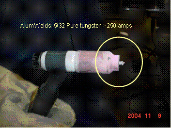
 WHAT HAPPENS WITH THE TIG TUNGSTEN AND ALUM WELDS? WHAT HAPPENS WITH THE TIG TUNGSTEN AND ALUM WELDS?
TIG Welding
Aluminum with pure tungsten and AC current. The AC, 50% SP - EN current
will result in a ball
at the tungsten tip, The rounded tip results from the high arc energy generated
from the 50% EP portion of the AC arc.
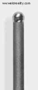
As mentioned with AC, the pure tungsten balls up,
producing a wider, less intense plasma arc cone that can result in arc wandering.
In contrast a rare earth tungsten used in combination with square wave technology that enables
a greater ratio of EN reducing the EP maintains a reasonable point and lets also allows the use of a smaller
tungsten. The result is a more focused arc, a more narrow and concentrated plasma, both of which improves the control of the weld plasma and weld bead profile. For a pointed electrode, use a truncated
(flat) point
as an overheated tip point can melt or fall into the weld.
More
benefits from TIG inverters with balance control & rare earth tungstens?
 Through
the benefits of balance AC control, some power sources allow up to 90 percent
EN in the AC cycle which when combined with variable output frequency (20 to 250 Hz) can dramatically
reduce the heat at the tungsten tip and direct the majority of electrons to the
work piece. This provides; Through
the benefits of balance AC control, some power sources allow up to 90 percent
EN in the AC cycle which when combined with variable output frequency (20 to 250 Hz) can dramatically
reduce the heat at the tungsten tip and direct the majority of electrons to the
work piece. This provides;
* Narrower heat affected zones
* Improved
control over weld depth-to-width ratios.
* Initiate the weld puddles much
faster.
* Faster weld travel speeds.
* Reduction in porosity.
* Less
tungsten and gas consumption.
* Eliminate arc wandering.
Aluminum
TIG Weld difficult application.
Question: Ed We are trying to AC - TIG weld a plug
in an Alum tube. The tube rotates. The tube is only 1/2 (12 mm) OD, and to
add to the problems it's only 0.050 thick. The plug is the same alloy, however
it's solid, 1/8 thick 3/8 in length and it fits in the end of the tube. The pulsed
weld is made between the plug surface and tube end. We have extensive GTAW issues
in controlling the weld fluidity in this single pass weld and frequently we melt
through the thin tubes.
TIG Welding Answer.
This is a
difficult, automated TIG application. The following adds to your weld issues.
[a] The tube is thin aluminum, rapid heat build up..
[b] The tube is
small diameter, rapid heat buildup.
[c] The plug thickness is different to
the tube creating different weld heat requirements.
[d] The plug length is
short creating rapid heat build up in contrast to the tube which is a good heat
conductor.
[c] AC with pure tungsten is used. The weld arc width and length
may change with variations in the tungsten length and the tungsten tip profile changes.
SOMETIMES
WHEN THE PROBLEM IS GENERATED BY WELD HEAT, THE TIG WELD SOLUTION IS MORE WELD
PASSES.
The answer to this difficult weld issue may lie in the opposite
of what you would expect. Instead of a high current single pass (single tube rotation)
weld you could try two or possibly three smaller weld passes.
[1] First start
out with a low weld current TIG pass. This weld pass will preheat the tube and
plug and reduce the alum oxides.
[2] For the second pass, slightly ramp
up the weld current, just enough to let the tube and plug alum melt and form a
weld.
[3] For the third pass if necessary, use one more tube rotation.
Use a lower current then the weld pass, this pass is to blend the weld.
[4] Ensure you use at least a 3 - 5 second current tail out with the finish weld
current less than 5 amps.
[5] The best weld equipment choice for this application would be to use a Balance Wave and
set the EN between 80-90%. and single pass welds would not be an issue.
~~
AC GTAW Arc Rectification~~
For those of you that use AC current
on your TIG aluminum applications and you may wonder about that occasional plasma
arc instability that may occur in the TIG arc. The following is a brief description
of AC arc rectification.
 During
the AC cycle, the tungsten is both positive and negative and the electrons flow
in two directions 120 times per-second from the tungsten to work and from the
work to the tungsten. First the tungsten in the negative mode is a superior conductor
than the metals being welding. When the AC cycle is in its negative mode the electrons
will flow from tungsten to work. During the negative mode we have more stable
electron flow than when the electron flow in the positive cycle in which the electrons
flow from negative alum metal surface to the positive tungsten tip. During
the AC cycle, the tungsten is both positive and negative and the electrons flow
in two directions 120 times per-second from the tungsten to work and from the
work to the tungsten. First the tungsten in the negative mode is a superior conductor
than the metals being welding. When the AC cycle is in its negative mode the electrons
will flow from tungsten to work. During the negative mode we have more stable
electron flow than when the electron flow in the positive cycle in which the electrons
flow from negative alum metal surface to the positive tungsten tip.
Another reason for AC rectification is the condition of the aluminum weld
surface. For example when welding multipass TIG welds one weld pass will remove
the alum metal surface oxide, the next pass made on top of the weld may present
a cleaner weld surface, (a weld surface that presents less surface oxides). When
the alum metal
surface has less impurities (less oxides) the HF used to reignite the AC arc may
have a difficult time as oxides add to arc stability, (that's one of the benefits
of oxygen or CO2 in a MIG gas to weld steel).
Remember it's the argon
gas molecules and tungsten positive cycle that provides the arc cleaning action.
The positive cycle is when the electrons flow from the work (breaking up the minuscule
aluminum surface oxides) to the tungsten, this provides the arc cleaning action.
Once the alum oxides have decreased from the weld surface its harder for the HF
to reignite the arc so we see arc stability issues also affected by the condition
of the alum weld surface.
Today we use square wave weld equipment to minimize
the effects of AC rectification however the arc rectification will still occur,
it's just less noticeable.
2009: Regular Manual and Automated TIG welds that
require filler metal is now obsolete.
Welcome to the TIP TIG process:
|
|