|
|
Welcome to the world's largest web site on MIG , Flux Cored and TIG. Weld Process Controls & Best Weld Practices. To get to the root cause of GMAW (MIG) & Flux Cored (FCAW) weld issues, requires Weld Process Control - Best Practice Expertise, & lots of Weld Reality. The site provides the MIG - Flux Cored and TIG weld information and data required to attain the highest possible manual and robot weld quality, always at the lowest possible weld costs.
This web site was first established in 1997 by Ed Craig. Contact Ed. ecraig@weldreality.com
Pulsed MIG EQUIPMENT and CONSUMABLES
comparisons and evalutions.
It was a play around industry which suffered decades of MIG weld process control ignorance, an industry that has been greatly influenced by weld sales influence. And then they introduced robots and a new process called the pulsed MIG into the same weld shops.
2005 Question: Dear Ed. I have been reading and educating myself on Pulsed MIG literature from the different weld equipment manufacturers. The different pulsed Wave Forms and pulsed MIG arc variations sounds fascinating and of course many weld and application promises are being made. My question is this. "How much should I rely on the pulsed MIG data that I have been reading"?
My Answer has been the same for more than 30 years:
If you are reading about pulsed MIG MIG weld equipment, the information on the performance and benefits of this weld equipment for carbon steels, low alloy and stainless steels may be as reliable as what you get on a used car lot, or as reliable as the above headlines provided by the world's largest newspaper, "USA Today".
Note: Right the correct News and left USA Today News.
WHEN A WELD EQUIPMENT MANUFACTURER CANNOT MAKE IT'S SOPHISTICATED, ELECTRONIC MIG EQUIPMENT, WELD COMMON APPLICATIONS AND PROVIDE SUPERIOR WELD QUALITY OR PRODUCTIVITY THAN IT'S LOWER COST, MORE DURABLE CV MIG EQUIPMENT, THAT EQUIPMENT MANUFACTURER HAS TO CREATE A SALES MARKETING INFLUENCED STRATEGY IN WHICH THEY MAY IMMERSE THEIR PRODUCTS IN MUMBO JUMBO BELLS AND WHISTLES, AND CREATE VAGUE WELD PROMISES WHICH THEY WILL RARELY BE ABLE TO PROOVE.
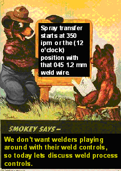
THE WELD EQUIPMENT MFG. WILL THEN PRESENT THE POWER SOURCE GLOSSY LITERATURE TO AN INDUSTRY THAT IN GENERAL LACKS WELD PROCESS CONTROL - BEST WELD PRACTICE EXPERTISE, AN INDUSTRY WHERE THE MAJORITY OF WELD PERSONNE WILL DAILY PLAY AROUND WITH THEIR WELD CONTROLS, AN INDUSTRY IN WHICH TOO MANY WELD DECISION MAKERS WILL RELY ON A SALES MAN FOR WELD ADVICE.
EXAMINE THE UNIQUE ABSURD MIG EQUIPMENT LANGUAGE BELOW AND YOU MAY RELATE .
Line up folks, for only $12,999.00, our unique, new Pulsed MIG Power Source provided;
[] ARTIFICIAL INTELLIGENCE.
[] FOZZY DE-WOOZZY PULSED.
[] SOFT AND HARD PULSED.
[] TRIPLE, PULSE ON PULSE ON PULSE.
[] AC ON TOP OF DC PULSED.
[] DYNAMIC RESPONSE PULSED.
[] ETHERNET CONTROLLED PULSED.
[] 5 MILLION PULSED WAVEFORMS.
[] PALM PILOT PULSED CONTROL, (IN THREE DIFFERENT COLORS) WITH GPS IF REQUIRED.
[] WIRELESS REMOTE CONTROLS FOR OUR PULSED WELDER.
And if you buy the top of the line unit, it actually welds metal.
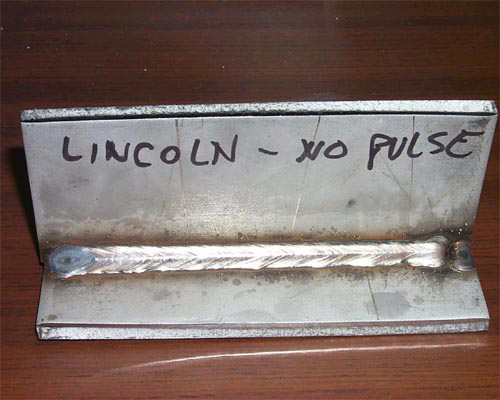
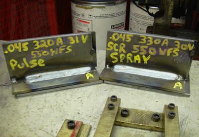
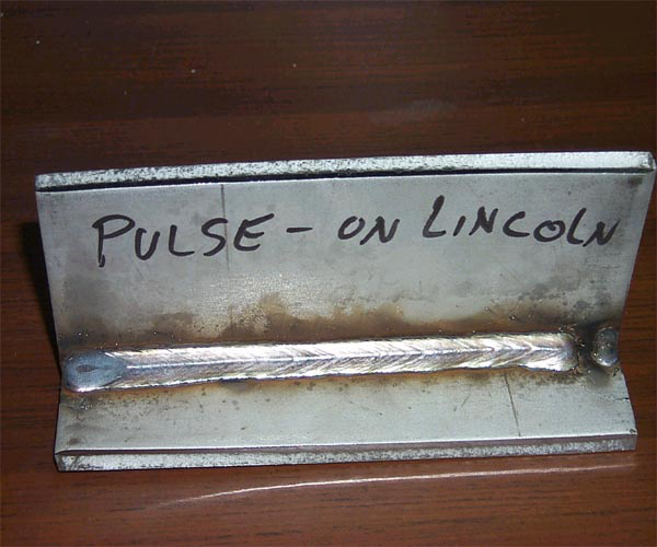
Heres a small dose of Weld Reality. When I made the optimum, MIG Spray fillet on the right. I did not have thick plate so I tacked together two thinner plates. I made this 7 mm fillet weld with a simple, two control, CV. $2500, MIG power source that has hardly changed since the 1960s. Using exactly the same techniques, I then made the inferior pulsed weld on the left. The welds had with the same wire feed rate and gas and that pulsed MIG power source came from Lincoln and cost approx. $12,000. Look close at the weld profile as it shows the weld puddle agitation and instabtilty that takes place with pulsed MIG when you want to use high wire feed settings that you would normally use with the lower cost CV equipment and the Spray mode..
Power Point from Ed's MIG process Control Training program
The only real problem with a MIG CV. $2000 - $3000 MIG power source, is minimal profits are generated for both the weld equipment manufacturers and the weld distributors with this type of equipment.
Even Ben would smile at some of the major
decisions in todays weld shops..
THE WELD BENEFITS OF ELECTRONIC BELLS AND WHISTLES IN PULSED MIG EQUIPMENT CAN SOUND IMPRESSIVE TO A WELD SHOP DECISION MAKER THAT HAS NO WELD PROCESS OWNERSHIP AND DOES NOT KNOW HOW TO CONTROL AND OPTIMIZE THE WELD EQUIPMENT ON THEIR WELD SHOP FLOORS OR IN THEIR ROBOT CELLS.
Note: There are four weld applications that can attain real world weld benefits from the pulsed process,
[1] automated weld cladding,
[2] automated 5G pipe welds,
[3] manual or automated aluminum applications < 4mm.
[4] applications in which spray transfer is too hot causing unnaceptable distortion..
Note: For those managers, engineers, supervisors and technicians that would rather optimize MIG and flux cored weld quality and productivity from low cost, more durable MIG equipment, all you need is the information in Ed's weld books and process control self teaching - training resources.
Another great benefit from low cost CV MIG equipment,
gas shielded flux cored wires were developed with this equipment:
In contrast to Inverters, Multi-process MIG machines and Pulsed
MIG equipment, that regular, low cost, more durable CV, MIG power source will always provide superior, all position,"gas shielded flux cored welds".
A WISE WELD MANAGER WOULD HAVE LEARNT FROM THE WELDING PAST.


.jpg)
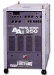
<2004 THE WORST MIG EQUIPMENT I WORKED WITH SO FAR IN NORTH AMERICA WAS MADE BY PANASONIC, MOTOMAN & LINCOLN.:
A friend of mine is in charge of Robots at one the largest Honda supply plants in the USA. He had over 200 robots and dialy struggled with numerous, never resolved Panasonic equipment weld issues. I was already aware that In 2004 the Panasonic pulsed MIG weld equipment he had to work with represented some of the most illogical, inconsistent, erratic weld equipment that had ever landed on North American shores.
In the many plants that I was asked to resolve robot weld issues, I used to squirm when I saw the Panasonic pulsed MIG equipment, as I knew that in many cases the weld issues in the plants would not be fully optimized till that weld equipment was replaced.
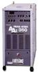
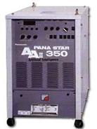
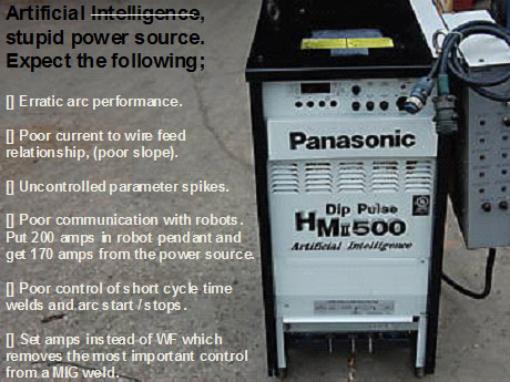
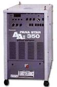
As the Panasonic MIG equipment is popular on Panasonic robots sold in North America, I thought I would spend some time evaluating what the Panasonic Pana Star AA2 - AA11- 350 and the HM 500 power sources had to offer. The following is a description of a verbal event that took place at an AWS weld show. The conversation is not word for word, however it represents the true content of the discussion.
The Panasonic sales rep provides his sales pitch at the AWS show, "Ed this dip pulsed power source is really unique. The power source provides "artificial intelligence". He continues.
"This power source is constantly analyzing the pulsed arc output weld data and making weld parameter corrections for the arc. In contrast to most other MIG equipment, this pulsed power source provides superior control of the weld penetration". The just out of college sales rep continues, "Ed, you may not be aware that with the earth quakes in Japan, " weld penetration in that country is now a prime issue".
The Panasonic sales rep was in his twenties and keen to provide me with weld advice and startling revelations about Japanese weld penetration issues. If you are new to this web site please keep in mind, I have worked with the MIG process for 40 plus years and with the pulsed process close to 25 years. When I first started evaluating pulsed equipment the Panasonic rep was approx. three years old, this did did not stop this rep from trying to educate me on the subject of welding.
The Panasonic rep then told me "that one of the things that effects pulsed weld penetration is when the pulsed arc length changes, as the arc length is shortened the pulsed drop may not be allowed to form without a short circuit interruption, this therefore effects the pulsed arc stability and consistency of the weld fusion attained" This poor sales rep did not realize that the problem he described had been a major issue with his equipment since it was introduced into the USA. He also did not realize that his artificial intelligent weld equipment that sat proudly on display at the weld show would reveal that it still could not provide a consistent pulsed weld arc especially on small weld cycle times.
WHY WOULD ANY WELD SHOP ACCEPT A MIG WELD POWER SOURCE THAT;
[A] PROVIDES INCONSISTENT, ERRATIC POOR WELD TRANSFER PERFORMANCE?
[B] GENERATES CONFUSION FOR THE USER,
[C] COSTS 100 - 300% MORE?
[D] MORE DIFFICULT TO REPAIR?
[E] HAS A MUCH SHORTER LIFE?
IF YOU HAVE SPENT MORE THAN 20 MINUTES AT THIS SITE YOU KNOW THE ANSWERS. IF YOU DON'T KNOW THE ANSWER, ITS FRED ON THE RIGHT.
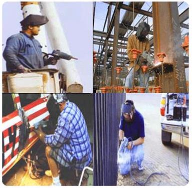
For the last four decades in ten different countries I have set up more than a thousand different MIG weld applications with focus always on attaining optimum, constant weld fusion and weld profiles that would always be called optimum. The MIG welds I have always produced would be made with traditional, MIG equipment that typically would cost 25% of the price of the Panasonic pulsed equipment.
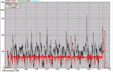
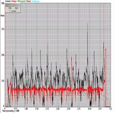
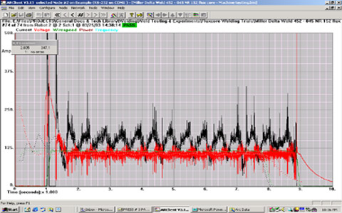
PANASONIC AND THE POOR WELD GRAPH: This oscilloscope chart shows voltage (red) and weld current (black) fluctuations taken by a frustrated Canadian weld engineer. He was frustrated because his Panasonic MIG equipment lacked the ability to produce two parts with the same weld appearance and fusion. The pulsed equipment was a Panasonic AA 11- 350.
Note on the chart. The dramatic swings of unstable prime weld parameters, with both volts and amps frequently hitting zero, this was too common an occurrence with many pulsed power sources built up to 2006.
The MIG welds I produced in 1960 and the MIG welds I will produce for companies in 2015 with with the little changed, traditional, low cost, durable, CV. MIG equipment, could pass
with process expertise, any global FILLET weld code requirement.
For over ninety nine percent of conventional manual and robot MIG welds on carbon or low alloy steel applications > 4 mm, you simply do not require a sol called Intelligent power source that provides a so called special ~~~Wave Form or unique Ripples~~~.
The traditional MIG equipment I have always utilized, was not electronically "intelligent", however when I provided weld process control training to tthe weld decision makers, you could assume that at the weld process control course completion, the weld personnel were "Process Intelligent" . These people were nd trained to make optimum MIG or Flux Cored welds with out playing around with controls and using unsophisticated MIG equipment.
The traditional MIG equipment I have utilized for 50 pluse years did have an unusual 50 year old electrical attribute common to all CV equipment. During the weld the CV MIG power source thanks to an optimum slope out put, instantly responds and makes a controlled current correction for the wire stick-out changes, (arc length variations).
Note with the left weld output oscilloscope, the traditional, lower cost CV, weld Amp - Volt stability, in contrast to the right graph where the same weld wire and similar weld parameters were used with the very electronic Panasonic AA 11-350.
Before purchasing your next power source, spend
a little time on the subject of weld process controls.
When asked for his opinion on weld fusion, and spray
versus pulsed, Albert might have said the following.
"Constant weld energy attainable from CV spray transfer is of course logical for consistent weld delivery and constant weld fusion. Wheras the inconsistent weld energy from the peak to back ground current of a pulsed power source will of course on certain applications lead to inconsistent weld fusion.".
< 2006 ARC LENGTH SENSITIVITY FACT:
In contrast to the pulsed mode in which one weld droplet per pulse cascades hopefully undisturbed across an arc gap, the traditional MIG spray weld transfer is "less sensitive to arc length variations" The simple reason for this is the spray transfer stream and does not require the formation of individual weld droplets to achieve optimum weld transfer.
In the pulsed mode, as the pulsed arc length shortens, the wire tip to work distance decreases and the pulsed weld drop will be eventually be disrupted as its in contact with both the positive wire and negative weld. This short circuit arc disruption can reduce the consistency of both the pulsed weld droplet transfer and weld fusion potential. Remember also this process spends fifty percent of it's time in a low back ground current of less than 80 amps. In contrast with traditional spray transfer, an arc length reduction has minimal impact on the delivery of the more consistent energy, spray transfer weld stream. With carbon steel welds particularly on metals > 5 mm when you want optimum and consistent weld fusion you figure out what process you should be using.
2006 NOTE: WITH CARBON STEELS AND HIGH DEPOSITION MIG WELDS DEPOSITED OVER 12 LB/HR, VIEW THE GREATER CONSISTENCY OF THE WELD TRANSFER AS EVIDENT IN THE SPRAY WELD SURFACE ON LEFT, VERSUS A 2006 PULSED WELD SHOWN ON RIGHT. PART OF THIS PROBLEM IS WITH THE PULSED WE HAVE THE INCONSISTENCY OF THE TRANSFER AND INSUFFICIENT CURRENT FOR THE WELD MASS:
The energy and configuration of a traditional MIG spray transfer plasma can also be superior to the pulsed MIG plasma reference the potential weld fusion profiles (side wall fusion) attained.
I did not get into a MIG arc plasma physics characteristic comparison with the Panasonic rep, as I know it would have been time wasted, any way he was to busy giving me welding advice.I however I did ask the Panasonic rep a simple question on the pulsed wire feed range. I said "does your intelligent power source provide a practical measurable benefit like extending the traditional MIG spray transfer wire feed range so that we can weld faster with a robot"?
The Panasonic rep instantly developed the infamous "weld glazed look", paused a few seconds, then replied. He stated he was not qualified to provide an answer. This was the first real thing he said to me after thirty minutes of verbal diarrhea.
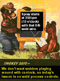
In 2006 and 2007 you too may be lucky enough to have discussions with some rep that wants to discus the attributes of pulsed MIG equipment artificial intelligence, yet it's likely this same individual will not know the weld deposition rate of a spray MIG weld made with an 045 wire at set at 450 ipm.
The Panasonic pulsed verbage again proves that when it comes to welding, "seeing the actual weld, is always mightier than the salesman's word".A few years earlier, at my first introduction to the Panasonic pulsed power source. I had a two hour lesson from another Panasonic rep that must have had least twelve months weld experience. This rep told me what he thought was the unique electronic benefits in his companies pulsed power source. In that time period the Panasonic power source was designed (or was it marketing strategy} to minimize the so called "ripple weld current output". Now keep in mind in that time for 30 plus years I had MIG welded with traditional CV weld equipment, yet with all the trillions of ripples I must have produced I have never produced a bad MIG weld or a weld with spatter issues. So you can imagine my surprise when I heard from Panasonic about the bad influence of the Panasonic "ripple output" .
TO ~~~RIPPLE~~~ OR NOT TO RIPPLE,
A PANASONIC WELD QUESTION?
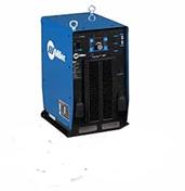
At the time of the Panasonic ripless power out put, I compared the rippless Panasonic power against a Miller DeltaWeld, which was a traditional, lower cost CV power source.By the way as this Panasonic was talking about ripples anyone could have put an oscilloscope on the Panasonic power source and see something that was much more of a concern than ripples. The Panasonic power source voltage (red) and current (black) was all over the place. The bottom line the standard, lower cost CV Miller power source (as shown above) proved to provide superior arc stability, more consistent weld energy and welds on > 0.125 that have a superior appearance.
Seven years later at another AWS show, I noted that the latest and greatest Panasonic Power source was using an 0.045 (1.2 mm) wire.
I asked the welder doing the Panasonic demo to set the wire at the traditional high spray transfer setting of 500 in./min. I noted while he was welding that the resulting pulsed arc plasma zone was narrow, agitated and the plasma was intense. The resulting pulsed weld had a poor convex profile that likely would have resulted in inconsistent side wall fusion. The bottom line. For the last two decades, when welding carbon steels I have been trying to find real world, practical, measurable welding benefits from the complex costly Panasonic power source and from other similar pulsed equipment, here today in 2005. I am still looking.
MILLIONS OF PULSED WAVE FORMS LATER AND THE SOPHISTICATED ELECTRONIC POWER SOURCES THAT MAKE THOUSANDS OF WELD DECISIONS PER SECOND AND WHAT DOES THE WELDING INDUSTRY END UP DISCUSSING FOR IT'S STEEL WELDS?
FUZZY DE WUZZZY / RIPPLESS / POWER THE WAVES / DIP-DE - PULSE / PULSE ON PULSED ON PULSE. PULSE ON 1/2 A BLOODY PULSED, ARTIFICIALLY INTELLIGENT, REMOTE WIRELESS CONTROLLED FROM YOUR CELL PHONE OR COMPUTERIZED PULSED WELDING EQUIPMENT.
I CRINGE AT THE THOUGHT OF WHAT THE FUTURE HOLDS FOR AN INDUSTRY THAT HAS BEEN SUCKED IN BY SO MUCH GIBBERISH.
E-mail from Brian.
Aug 2005.Ed: Have you heard that it's impossible to modify Panasonic robot settings to program weld parameters in WFS? which is something you can do with Motoman or ABB robots. Further, since even their newer tach-drive units they don't have any WFS readout or setting, you still can't calibrate the robot in WFS (without a separate device). I've exchanged a number of very in-depth e-mails with Panasonic on these two closely-related issues during the last 10 months. Currently Panasonic seems incapable of grasping the facts that calibrating in AMPS inherently introduces inaccuracy and cell-to-cell variations that strongly inhibit establishing a continuous improvement effort in high-level optimizing of parameters. Programming in AMPS lies to the programmer about what he's adjusting, masks the whole balance of joint-fill-volume vs. travel speed, and makes it more difficult to teach MIG process troubleshooting and process improvement to anyone.
Going far beyond my professional duty in attempting to assist Panasonic, I have presented several arguments of ironclad logic which clearly point out why WFS calibration would be far more accurate, than AMPS calibration. So far, they still don't get it. And with Panasonic being so devoid of in-depth process expertise in North America, I'm certainly not holding my breath. So far, the only weld engineers I've met who like PFA welding systems are either self-proclaimed welding experts with no degree in the field, or OSU welding engineers who typically wet behind the ears and are incompetent in weld process expertise.Best Regards. Brian.
From Ed's CD Process Control Training Program

Ed's Reply. If you have time to waste and want unnecessary weld complexity in your world, consider a Panasonic robot cell. Brian I brought up the WF and amp issue with Panasonic in the early nineties, unfortunately, when it comes to MIG weld process controls the people I dealt with at Panasonic were sadly lacking expertise on the subject.
You may be interested in a recent experience I had with Panasonic. In January 2006 I was asked to reset the Panasonic robot programs for a company in PA. The Panasonic robots were approx. 12 months old. At this company the touch sensing and through the arc tracking was not working correctly and as usual the pulsed process was not suited to the steel application. I switched the pulsed power source over to the spray transfer mode and with the Panasonic 500 pulsed equipment. To attain 270 amps I had to set 370 amps in the Panasonic robot pendant. By the way I figured for every hour it took for the programmer to make changes with the Panasonic weld and robot data, I could have done the same thing in 15 minutes with an ABB robot. There is only one way to control a MIG weld and that is through control of the wire feed.
~~~~~~~~~
~~~~Burp~~~~
TO FURTHER SCREW UP THEIR CONFUSED CUSTOMERS AND MAKE LIFE MORE COMPLEX FOR WELD SHOPS,
PANASONIC WAS MORE THAN UP FOR THAT TASK?
For it's sophisticated pulsed MIG equipment, Panasonic is proud to claim it provides "Four Million Wave Forms". A MIG Weld Reality. Irrespective of the pulsed or traditional MIG transfer weld modes utilized, once the wire size is selected, optimum welds can be made on every carbon steel, alloy steel and stainless application with "Four simple weld settings".THE PROBLEM IN MANY WELD SHOPS IS THE WELD PERSONNEL DONT KNOW THOSE FOUR OPTIMUM WELD SETTINGS, THEY ARE IN MY Books & Process Control - Best Practice TRAINING RESOURCES.
From Panasonic the "Pana Star AA2" Panasonic increases the power source CPU'S for faster arc response from this artificial intelligent power source. Panasonic claims this Fuzzy logic, MIG power source offers electronic wonders. The weld reality, is the welds this power source produces are inferior to short circuit or spray transfer welds made from a traditional CV. MIG power source that costs 50 to 70% less.
Japanese weld logic and European and USA
weld logic are simply not the same.
[] For weld shops considering the purchase of a robot, remember at the end of the day it's not about the robot or MIG weld equipment electronics, it's about the weld quality and productivity produced.
[] For those companies that do low to medium volume, ever changing steel / stainless weld applications, give serious consideration to the following;
[] When you examine each robot manufacture's product don't get caught up with the bells and whistles and fancy electronic pulsed MIG power source with it's 4 million wave forms. Stay focussed on the MIG power source weld output and communication with the robot, the weld arc consistency at high and low wire feed rates and don't forget the equipment durability.
[] With the robot program, examine the length of time required to both program a part and to make weld changes to the program.
[] With the robot program, examine the ease in which wire feed, voltage or pulsed parameter changes are made.[] Examine the logic in the robot's weld program and the calibration between pendant and power source weld data.
[] Examine the robot's automated tool center point TCP capability and repeatability.
[] Examine the robot's touch sense and through the arc tracking capability.
[] Examine the robot weld weave program, especially the logic of the program.
[] Examine the accuracy and repeatability of the robot with the "positioner".
[] Examine the complexity of programming the robot to work with secondary equipment such as the positioner, a camera or torch cleaning stations.
[] Examine the robot instruction literature, the technical support and service capability.
REMEMBER BECAUSE THE ROBOT YOU ARE CONSIDERING SEEMS TO WORK WELL IN AN AUTO PLANT, THAT THIS IS A LOCATION WHERE THEY THEY MAY RARELY CHANGE THE WELD PROGRAMS AND THIS IS AN ENVIRONMENT THAT TOO OFTEN HAS MINIMAL WELD EXPECTATIONS.
IN A JOB SHOP, CONSIDERATION SHOULD BE REQUIRED FOR THE SPEED AND SIMPLICITY REQUIRED TO PROGRAM DIFFERENT PARTS. ALSO THE ROBOT TOUCH SENSE AND WELD TRACKING CAPABILITY IS A CRITICAL FEATURE FOR MANY APPLICATIONS.
NOTE: IT TYPICALLY TAKES 30 TO 50% MORE TIME TO PROGRAM A JAPANESE ROBOT THAN IT DOES TO PROGRAM AN ABB SWEDISH ROBOT..
.
.
As I am impressed with weld logic, ease of use and performance.
My first choice for a robot would always be ABB.
.
After evaluating MIG equipment for decades,
I KNEW THAT LINDE - PRAXAIRE - (UNION CARBIDE) BUILT
THE WORLD'S BEST CV MIG WELD EQUIPMENT.
LINDE VI 252 A LOGICAL, DURABLE CV MIG WELD UNIT.
> 1980s. As with most Union Carbide - Linde equipment, the Linde VI 252 MIG power source and two large size rolls wire feed unit was and still is a gem for and weld shop weld gage to 6 mm. This is the MIG unit that the weld shop could expect to last for at least two decades without problems. This unit had an excellent Slope Out put, provided great short circuit and spray welds. This power source was considered a medium size MIG unit, providing 250 to 300 amps. The wire feed was also a work hors with it's permanent MAG motor and it's two over sized drive rolls. The wire tension and drive on this unit developed over two decades ago is better than any four drive roll units sold in 2015.
COMPANIES WHO CAN GET PAST WELD EQUIPMENT SALESMANSHIP AND PROVIDE THEIR EMPLOYEES WITH WELD PROCESS TRAINING CAN PURCHASE TRADITIONAL, LOW COST MIG EQUIPMENT AND PRODUCE CARBON STEEL / STAINLESS MIG WELDS THAT WILL MEET THE MOST STRINGENT, GLOBAL WELD QUALITY STANDARDS.
E Mail from nick@victoryteam.comHI ED.
MY GOD ITS REFRESHING TO HEAR SOMEONE TALK STRAIGHT ABOUT MY FAVORITE SUBJECT. I USED TO FABRICATE RACE CAR CHASSIS AND IN MY QUEST FOR THE ULTIMATE MIG MACHINE I SELECTED THE MILLER MAXTRON AND THE INVISION. I HAVE BEEN DISAPPOINTED WITH BOTH POWER SOURCES AND COULD NEVER GET ANYTHING NICE GOING ON IN THE PULSED MODES. MY OLD MILLERS WERE SO UNBREAKABLE AND ALWAYS PROVIDED GREAT WELDS. ALL YOU HAVE SAID ABOUT THE NEW ELECTRONIC, MIG EQUIPMENT JUNK, I HAVE EXPERIENCED.
REGARDS AND KEEP UP THE GREAT WORK. NICK.
.
We would not have a variety of substandard weld equipment
if we had good weld management.
GLOBAL WELD MANAGEMENT APATHY..
IN THE NINETEEN EIGHTIES, A.O SMITH THE WORLD'S MOST SUCCESSFUL AUTO / TRUCK FRAME MANUFACTURER WAS COMPANY LOCATED IN MILWAUKEE.
A.O.SMITH STARTED OUT MAKING CAR FRAMES FOR CADILAC IN 1904. IN 1990s A.O.SMITH WAS THE ONLY GLOBAL CORPORATION TO ESTABLISH ROBOT MULTI-PLANT WELD BEST PRACTICES AND ALSO PROVIDE EFFECTIVE ROBOT PROCESS CONTROLS. THE AOSMITH DAILY ROBOT WELD REWORK FOR THE CAR AND TRUCK FRAMES WAS MINUSCULE AND IN CONTRAST TO MANY ROBOT COMPANIES WELDING IN 2008, THEIR ROBOT MIG PRODUCTION WAS BOTH OPTIMUM AND CONSISTENT.
In North America during the mid 1990's, A.O.Smith had more than 1200 ABB robots which were utilized mostly with Miller Delta Weld 450 CV MIG equipment using mostly 0.045 (1.2 mm) MIG wires. The majority of the welds produced were made with the spray transfer mode at MIG weld deposition rates that averaged 11 - 14 lb/hr.
Note: AS ITS BEEN FOR DECADES, IN 2018, THE MILLER CV DELTA WELD 450 IS STILL THE WORLD'S BEST PERFORMING MOST DURABLE, AND MOST COST EFFECTIVE CV MIG POWER SOURCE.
After welding frames for 93 years, around 1997, A. O. SMITH was purchased by Tower Automotive. I have been in many Tower plants, and my experience led me to sincerely believe that the "HANDS OFF, Tower corporate engineers and managers never fully comprehended or appreciated the weld process control expertise that A.O. Smith utilized in the management of its robot weld cells.
Today thanks to typical hands off management that you will find at automotive companies like Tower Automotive, and thanks to the lawyers we call politicians in Washington, through no fault of their own, American workers are fast loosing their future ability to earn a decent wage.
IT'S SAD IN THIS APATHETIC MANUFACTURING ENVIRONMENT THAT AN AMERICAN MANUFACTURING GIANT LIKE TOWER ADDED TO AMERICA'S FUTURE POTENTIAL EMPLOYMENT ISSUES THROUGH POOR MANAGEMENT. TOWER TOOK A PROUD 90 YEAR OLD COMPANY, AND IN LESS THAN 90 MONTHS BROUGHT THEM TO CHAPTER 11.
IN 2018 THERE WAS NOT ONE GLOBAL AUTO / TRUCK FRAME PLANT OR SUPPLIER THAT HAS COME CLOSE TO ATTAINING THE SAME OPTIMUM DAILY ROBOT WELD PRODUCTION AND QUALITY ACHIEVED BY A.O.SMITH IN 1988.
20I5: BEST WELD PRACTICES AND WELD PROCESS CONTROLS: 50 PLUS YEARS AFTER THE DEVELOPMENT OF MIG EQUIPMENT, THERE IS LESS THAN A HANDFUL OF COMPANIES IN NORTH AMERICA THAT HAVE IMPLEMENTED MULTI-PLANT MANUAL / ROBOT BEST MIG WELD PRACTICES.
2008 WELD COSTS: I BELIEVE THERE ARE LESS THAN 100 COMPANIES IN NORTH AMERICA THAT ACTUALLY KNOW THE REAL COST OF A MIG WELD PRODUCED ON THEIR WELDED PARTS.
ALL THAT'S REQUIRED FOR MANUAL BEST WELD PRACTICES, WELD COST CONTROLS AND ROBOT PROCESS CONTROLS IS FOR MANUFACTURING MANAGEMENT AND ENGINEERS TO TAKE RESPONSIBILITY FOR THE WELD DECISIONS AND EQUIPMENT IN THEIR PLANTS. TRY THESE RESOURCES.
[] Robot management and engineers who are not responsible for the processes they own.
[] Managers and engineers who cannot build steel parts and hold 1 mm tolerances.
[] Designers who don't understand the weld process limitations on their parts.
[] Engineers who produce poor weld fixtures.
[] Managers, engineers and technicians who don't seek the necessary MIG process control education or training.
Lets face it, you don't have to look too far today in a manufacturing plant to find a management or engineers that lacks weld equipment or weld process control "depth". . and in any auto / truck plant, it would not take more than two minutes to find an individual that believes they are an expert on a subject as they have 12 months experience.Note: MIG has been around for fifty plus years, it has two weld controls. If you are a manger or engineer who cannot understand those controls, you now know what you have to do.
20I5: BEST WELD PRACTICES AND WELD PROCESS CONTROLS: 50 PLUS YEARS AFTER THE DEVELOPMENT OF MIG EQUIPMENT, THERE IS LESS THAN A HANDFUL OF COMPANIES IN NORTH AMERICA THAT HAVE IMPLEMENTED MULTI-PLANT MANUAL / ROBOT BEST MIG WELD PRACTICES.
2008 WELD COSTS: I BELIEVE THERE ARE LESS THAN 100 COMPANIES IN NORTH AMERICA THAT ACTUALLY KNOW THE REAL COST OF A MIG WELD PRODUCED ON THEIR WELDED PARTS.
ALL THAT'S REQUIRED FOR MANUAL BEST WELD PRACTICES, WELD COST CONTROLS AND ROBOT PROCESS CONTROLS IS FOR MANUFACTURING MANAGEMENT AND ENGINEERS TO TAKE RESPONSIBILITY FOR THE WELD DECISIONS AND EQUIPMENT IN THEIR PLANTS. TRY THESE RESOURCES.
WELD PROCESS OWNERSHIP DOES NOT START WITH:
[] Robot management and engineers who are not responsible for the processes they own.
[] Managers and engineers who cannot build steel parts and hold 1 mm tolerances.
[] Designers who don't understand the weld process limitations on their parts.
[] Engineers who produce poor weld fixtures.
[] Managers, engineers and technicians who don't seek the necessary MIG process control education or training.
Lets face it, you don't have to look too far today in a manufacturing plant to find a management or engineers that lacks weld equipment or weld process control "depth". . and in any auto / truck plant, it would not take more than two minutes to find an individual that believes they are an expert on a subject as they have 12 months experience. MIG has been around for fifty plus years, it has two weld controls. If you are a manger or engineer who cannot understand those controls, you now know what you have to do.
A. O SMITH.
A ONCE PROUD AMEICAN MFG: In North America during the mid 1990's, A.O.Smith had more than 1200 ABB robots which were utilized mostly with Miller Delta Weld 450 CV MIG equipment using mostly 0.045 (1.2 mm) MIG wires. The majority of the welds produced were made with the spray transfer mode at MIG weld deposition rates that averaged 11 - 14 lb/hr.
Note: AS ITS BEEN FOR DECADES, IN 2018, THE MILLER CV DELTA WELD 450 IS STILL THE WORLD'S BEST PERFORMING MOST DURABLE, AND MOST COST EFFECTIVE CV MIG POWER SOURCE.
After welding frames for 93 years, around 1997, A. O. SMITH was purchased by Tower Automotive. I have been in many Tower plants, and my experience led me to sincerely believe that the "HANDS OFF, Tower corporate engineers and managers never fully comprehended or appreciated the weld process control expertise that A.O. Smith utilized in the management of its robot weld cells.
Today thanks to typical hands off management that you will find at automotive companies like Tower Automotive, and thanks to the lawyers we call politicians in Washington, through no fault of their own, American workers are fast loosing their future ability to earn a decent wage.
IT'S SAD IN THIS APATHETIC MANUFACTURING ENVIRONMENT THAT AN AMERICAN MANUFACTURING GIANT LIKE TOWER ADDED TO AMERICA'S FUTURE POTENTIAL EMPLOYMENT ISSUES THROUGH POOR MANAGEMENT. TOWER TOOK A PROUD 90 YEAR OLD COMPANY, AND IN LESS THAN 90 MONTHS BROUGHT THEM TO CHAPTER 11.
IN 2018 THERE WAS NOT ONE GLOBAL AUTO / TRUCK FRAME PLANT OR SUPPLIER THAT HAS COME CLOSE TO ATTAINING THE SAME OPTIMUM DAILY ROBOT WELD PRODUCTION AND QUALITY ACHIEVED BY A.O.SMITH IN 1988.
MILLER DELTA WELD: I believe that for the last few decades. the world's most cost effective, best performing MIG power source has been the Miller Delta Weld 450.< 2005: When you decide to evaluate a pulsed MIG power source for welding carbon steel and stainless welds, you should compare the pulsed weld results you attain with the the weld resulats from an optimum, CV MIG power source that will cost much less and last much longer..
In many different manufacturing plants in different countries, for close to two decades, I religiously recommended the purchase of the world's best traditional MIG power source, the Miller Delta Weld 450, and never got a thank you note from the folks at Miller.
I took the Delta Weld equipment to Thailand to MIG and flux cored weld 270 ksi armored plate on USA made army tanks. While Miller equipment was not sold in Spain, I encouraged a Spanish auto parts supply company, Viza (Citroen BMW car seats) to purchase the Miller Delta Weld 450 equipment for it's new robot lines. The bottom line is I recommended the Delta Weld equipment for hundreds of manual / robot applications across the USA and Canada and in many countries.
The Delta Weld was extremely well built and unique in that it provided an optimum slope parameter output for both short circuit and spray transfer modes. This durable power source also provided excellent arc starting characteristics. MIG arc starts used to be a common issue especially with Lincoln's MIG equipment. The bottom line the Delta Weld was a durable, cost affective work horse for manual MIG welding and a logical power source to put on robots for all steel welds.
HOW ENGINEERS AT WELD EQUIPMENT MANUFACTURES WHO TYPICALLY KNOW LITTLE ABOUT ARC PHYSICS AND WELD REQUIREMENTS, OR OPTIMUM WELD DATA CAN SCREW UP GOOD MIG WELDING EQUIPMENT.
MILLER, PLEASE TRY NOT TO screw up thAT Delta Weld. Around 1998 or 1999, some individual at Miller, possibly a new electronic engineer or an inexperienced product manager, decided some cost cutting changes could be made to this power source. The Delta Weld changes had a negative impact on the slope output effecting the weld equipment performance. I believe that the person who made the changes probably did not know what the optimum current / wire feed relationship is for the common MIG wires and weld transfer modes, or what the ideal weld current, wire feed relationship is for welding a simple 1/4 fillet with an 0.045 wire. Anyway who ever got their hands on the Delta Weld took a weld giant and created a mundane product readily available at the competition.
THE MILLER WELD EQUIP. MANAGEMENT ALLOWED THEIR POWER SOURCE ENGINEERS TO REDUCE THE PERFORMANCE OF THE WORLD'S BEST MIG POWER SOURCE, THE 450 DELTA WELD.
During 1999, I provided weld management consulting and training services to a company called Omniquip. This company made SkyTraks. At the time Sky Trak used Lincoln MIG equipment. I wanted to improve the welds and the equipment on the shop floor so I has Ominiquip ordered 4 Miller Delta Weld 450 power sources for the companies weld training facility.
Typically the Delta Weld had an excellant slope output and would last for one to two decades without equipment or performance problems. However with these new Delta Weld units, In the next six months this Miller equipment resulted in;
[a] Numerous "wire feed" electronic issues with 3 of the 4 new power sources.
[b] In contrast to the traditional Delta Weld power source, these 1999, 450 power sources, revealed that the weld voltage and current per/wire feed rate (slope output) had been altered. The result was a negative influence on weld fusion potential and on the power source performance.
[c] For low current MIG applications, the Delta Weld power source when using "a low energy argon mix" could now no longer provide low current, consistent arc starts.
Note: A primary weld concern with MIG welding equipment is attaining sufficient weld energy for the wire feed rate delivered. For example the slope output (volt amp curve) is designed to provide a specific current for a given voltage. Also the slope of the curve will determine the amount of weld current change per volt change.
How important is the MIG Volt / Amp / Wire Feed / Weld Deposition relationship?
For example, with a traditional, effective CV power source, when using an 0.035 wire at 210 ipm, delivering 3.3 lb / hr, the CV power source would put out approximately 140 amps and require 17 welding volts. This weld parameter combination provided both optimum LOW weld voltage and current for the short circuit wire feed rate selected. If a power source designer changes the slope, lets say the required short circuit weld voltage for that wire feed position is now 19 volts. As a result of the extra voltage, the short circuit weld droplet size is now larger, more globular and the short circuit weld transfer would be more erratic with excess spatter.
It seems in their quest to add electronic bells and whistles, some MIG power source designers forgot about the fundamental Arc / Slope and Wire Feed relationshipnecessary for optimum MIG weld transfer. When a power source designer makes negative changes to a power source that for decades has been perfect, one has to ask what is the weld equipment manufacturers motive?
[a] Is it weld process ignorance?
[b] Is the need to reduce the weld equipment cost?
[c] Is it the need to add electronic bells and whistles to justify a future power source price increase?
The Miller Weld Power Source Manager told me that that when he tests MIG
equipment he "plays around " with the MIG weld controls"
While talking to the Miller MIG product manager about the slope performance and the necessary relationship between the wire feed and parameter setting, I noted the Miller manager had a glazed look. That glazed look is one I have seen many times as it was usually on my wifes face when I talked to her about welding.
The Miller MIG power source product manager's response to my complaints was, "he had no problems with the revised Delta Weld 450 power source, and reference the weld parameter / wire feed differences i had shown him, he could not understand my concerns, becuase when he makes welds he just "plays around" with the weld controls till he finds a weld setting he likes.
.
Question. Did the engineers who built the new revised Delta Weld equipment check the revised performance with all the common available argon mixes before sending the equipment out to welding shops?
Question. Did the Miller management believe it was important to hire a MIG product manager who did not understand the MIG process, a man who had to "play around" with the two simple controls on the MIG weld equipment.?Question Did the Miller management believe that when they build products that their customers should test it.
A 2003. MILLER DELTA WELD 450 / 452 UPDATE.
Due to the poor welding performace of the KOBELCO MIG equipment thats usually found on MOTORMAN ROBOTS, in 2003, I had to get one of my clients that uses the Motoman robots to switch over from the KOBELCO 350 MIG power source to a MILLER, DELTA WELD 452. The 452 is basically a 450 power source with a built in interface that can communicate with robots. The 452 unit I tested at this company provided excellant weld performance on this application, the performance that the < 1999 Delta Weld used to provide.
SOMEONE AT MILLER MUST HAVE BEEN TAKING NOTES AT THIS SITE AND QUICKLY MADE THE CORRECTION TO GET THE DELTA WELD PERFORMANCE BACK TO WHERE IT WAS. THEY DID NOT SEND A THANK YOU CARD.
MILLER INVISION 456MP
From Miller. Invision 456MP.Electronics and Weld Mediocrity.
If you have nearly $6000 to waste on poor performance and a poor slope out put, take a look at the Miller Invision 456MP. However If you wanted to save well over $3000 you would bring in a Miller CP 302. Then spend a few $ on my books and Cd process control training resources. With the lower cost Miller unit and process control expertise you will attain the weld quality and productivity you desire..
Miller Auto Axcess.
I think this next e-mail tells a great story about Miller and weld equipment Bells and Whistles:
E.Mail from Greg. April 2005.
Ed. The following is my experience and my frustration since owning 7 Miller Auto Axcess 450 machines for almost one year. My boss at Magna believes my job is to get the GM robot welded parts out of the door without weld quality or production issues, however with all the Miller issues I have had to put up with, I feel like less like a robot technician and more like an unpaid Miller Weld Equipment Technician. Ed what happened to the good old days when you switched the Miller DeltaWeld on and got through the shift without welding the following issues?
1) We were told by Miller that their Accupulse would weld faster than traditional CV equipment and produce less spatter, (i guess this is what happens when you listen to a salesman),
3) We had excessive contact tip wire burn back issues when using Accupulse. I could not get more than 2-3 hours of production without an arc fault due to a wire burn back. We had lots of evidence of micro arcing on the weld wire.
4) To try and help stabilize the process and also to reduce the tip burn backs, Miller sent us a custom Accupulse program twice. Miller attempted to limit the peak current at the arc start to prevent the micro arcing and tip burn backs. This never worked properly and I still had the burn back problems.
5) I have now updated core system software in these machines 3 times in the short time we have owned them.
6) Finally after taking your advice, I turned off the Accupulse to the CV mode. That Accupulse mode was daily costing Magna excessive production downtime and extensive weld repairs on welds that were unstable.
7) When running in the traditional CV mode we were able to get the travel speeds thirty percent faster 40 IPM than the Accupulse mode.
9) We were getting intermittent "Wire Stuck Alarms" when we did not have wire sticking conditions. Miller's response to this was that there was a timing issue between the robot and the welder causing erroneous nuisance alarms. It may occur if the tip of the wire scrapes on the part after a weld was complete, even though the robot was not stuck and on the way to its next weld or its home position. Miller told me to disable this alarm to avoid nuisance occurrences.
10) We continued having excessive amount of "Arc Shortage Alarms" on the Motorman XRC robots. The Arc Shortage alarms are things coming in from the welder after getting a legitimate arc ignition. The welder was logging an excessive amount of wire feed speed errors for no apparent reason. Each time the welder felt it had a wire feed speed error; it would send an alarm to the Motoman XRC causing the Arc Shortage alarms.
a) Miller ended up turning off the Wire Speed Error alarms in the machine because they felt these alarms were nuisance only causing excessive faults on the robots.
12) On a few machines I had the Inductance set to 60 on a 0-100 scale. Miller's default inductance setting is 30. I did this on short circuit welds to get a better wetting action and better bead appearance. Miller decided to set all the welders at an inductance of 30. They felt that a 60 inductance may have been too high causing harsh arc starts. After turning the machines down to 30 inductance, we had to change the arc start conditions in the robots and reduce the start voltage. I had higher than normal starting voltages when using 60 inductance to prevent machine gun type starts.
13) Millers approach to its numerous equipment issues was to bring in a new pulsed power source, the Auto Axcess 300. My application is on 1.8mm and below down to 1.0mm. We are using 0.035 wire with a 92-8 Ar-C02 gas mixture.
a) Miller told me that the Auto Axcess 450 machines have a peak short circuit starting current of around 700 amps. They felt that this was much too high for an 0.035 wire causing the micro-arcing conditions.
b) The Auto Axcess 300 machines have a peak short circuit starting current of around 500 amps which they felt would be better for welds done less than 200 amps using 0.035 wire.
c) Miller turned down the run-in settings to 50 IPM from the 250 IPM I had set. They wanted the wire to run-in much slower while attempting to strike the arc. I started at 100 IPM when we first bought them and tried various settings between 100 and 275 IPM with no real changes noticed.
d) Miller also set the wire retracts at the end of the weld to 100 IPM for 0.2 sec. This is done at each arc off automatically by the welder to ensure the wire is not touching the part at the next arc strike.
Note From Ed. Greg has the patience of a saint. I believe his company should have replaced the MIG equipment with the 452 and taken Miller to court for the production costs invloved. Miller did not learn from this and keep in mind Magna is likely the worlds largest supplier of auto - truck parts. Scroll down to see that years later the Miller Axcess fiasco continues.
Note from Ed. WANT TO CUT DOWN ON WELD SHOP FRUSTRATION? DON'T BUY ELECTRONIC MIG EQUIPMENT TILL YOU TEST THE HELL OUT OF IT AND MAKE SURE THAT THE MODEL YOU PURCHASE HAS BEEN AVAILABLE TO WELD SHOPS FOR AT LEAST 3 YEARS.
.
Jan 21-2007: E-Mail to Ed Craig.
Reply From Ed:
[1] First as you and I are not electronic engineers, you should consider setting your companies lawyers on Miller for selling equipment that does not function correctly.
[2] Perhaps your managers and engineers could also read some of the info at this site before making important and costly MIG weld equipment and process decisions.
June 2005 E-mail to Ed.
.
From Ed. What's that old song that
has a line, "when will they ever learn"?
Ed having the same Miller Axcess problems in Spain 2008.
The plant in 2008 ordered the Miller Axcess for it's robot cells. Its first problems were arc start and contact tip issues. Sometimes 13 contact tips a shift were being changed. I knew that Miller has known about this problem for at least three or four years and still has not fixed the problem. My client wants to get rid of the new Miller Axcess, however Miller adds to the problem by no longer making the Delta Weld equipment available with a robot interface. By the way what a useless toy the Miller Palm pilot is, its another tool that will ensure people waste the day "playing" around with useless bells and whistles..
Ed's Answer Zhu, The crater and control of the weld end data has been an on going problem for years with this equipment. I have devised unique programming and process solutions for these issues. You will find them in package 4 of my robot process control resources.
Rememeber Miller is one of the better MIG weld equipment manufacturers, Yet with the apathetic Miller management in this time period, it seems they need years or decades before they respond to their MIG equipment issues, and usually without recalling their faulty products and rarely informing their customers The bottom line as its always been, the weld shops pay the price for the poor weld equipement produces. Boy I hope in the next life I can keep this weld expertise and be reborn as a lawer, because I know many companies that have lost millions due to weld equipement problems. Just to show you how long this Miller BS has been going on, take note of this Auto Axcess email in 2013.
Miller Auto Axcess: Jan 2103:
E-Mail. Ed. We have had arc end weld issues with 2 Miller Auto Axcess 450 D.I's in a dual arm Motoman cell since the insallation. It seems the Auto-Axcess Sharp-Start routine is causing small explosions at the weld ends. These explosions can be heard and seen as little balls of molten metal shoot out of the cell at the arc ends and some times cause micro crater cracks little "snowman" looking eruptions that have to be ground off and manually repaired. We needed assistance se we called in the Miller rep.When the regional Miller rep came to our plant he first blamed the weld wire. Then he blamed the gas mix, the gas flow rate, the weld voltage, wire feed speed and the wire stick-out. He then blamed the raw materials we were welding and then followed with we should change all the weld schedules from DC Spray Mig to AccuPulse. With nothing working for this joker, he finally he decided that thee smooth drive rolls on the metal-cored wire was the problem. More to the point, I asked repeatedly if he could turn off the Sharp-Start and auto burnback "features" he said we would have to talk with the Miller Engineer responsible for the Auto Axcess line.
Do you know what we need to do to disable these "special features" so I can use normal crater fill and burnback techniques? By the way we weld only 3/4" Hot-Rolled plate and its a railroad application. All the robot welds are in the 2F position, 3/8" single pass fillet.
The gas and voltage lets us burn through the mill scale pretty well and we have used these parameters for years in manual welding with regular CV equipment.
Our weld data is as follows.
Wire: Select-Arc Select 70C6 .062.
WFS: 330 IPM.
Voltage: 28.5.
Gas: 80Ar/20Co2.
Flow Rate: 40 - 50 CFH.
Wire Stick-Out: 3/4 - 7/8
Travel Speed: 40 cm/min
Thanks In Advance. Jeff Christensen. Mfg. Eng. Progress Rail Services.
THE MILLER CONTINUUM.
USA 2015: Its 2015, in contrast to the lower cost, more durable Miller CV >350 amp CV unit that will cost approx. 50% less, we now in 2015 have the Miller Axcess evolution and its called The Continuum. With this so called advanced pulsed MIG unit, we have yet another Miller power source that could not provide me any real world weld benefits for the vast majority of steels, low alloy steels and stainless welds,
Don't waste money on bells and whistles, use these process control self teaching / training resources that cost $300, and instead of wasting money on that >$7000 advanced MIG power source, you can save $3000 and attain the same weld quality and productivity.
Where the hell has the weld current gone
?
Miller Invision, XMT or Accupulse.
What happens when you use the regular short circuit or spray transfer MIG modes with this equipment? Inverters, pulsed and multipurpose CC/CV MIG equipment typically provide a steeper slope than traditional CV equipment, restricting the typical weld current output. The current reduction from this equipment can result in sluggish welds (poor weld fusion) or welders welding in the globular mode when they should be in spray transfer. If using this equipment with low energy argon - oxy or argon < 9% CO2 mixes, these gas mixes as you know require low weld voltages and will further lower the potential weld current output.
WELD EQUIPMENT COMMENTS.
ESAB Aristo 450. This multipurpose pulsed inverter provides two different features worth evaluating. The power source has a built in water circulator for water cooled guns. It also has if you feel you need one, an "arc data monitor" The Bottom line. This MIG power source provides good weld characteristics, however for 99% of your welds you will never need most of the bells and whistles found on this costly equipment.
MANUAL OR ROBOT WELD POWER SOURCES DO NOT REQUIRE "ARC DATA MONITORS". WELD SHOPS HOWEVER DO REQUIRE WELD PERSONNEL WHO HAVE WELD PROCESS EXPERTISE AND WELD MANAGEMENT WHO BELIEVE IN EQUIPMENT OWNERSHIP, BEST WELD PRACTICES AND WELD PROCESS CONTROLS.
ABB Robots and ESAB Arcitec Weld Issues.
Robot Welds on Ford 6061 Aluminum Car Seats.
During 2000, I was requested by an engineer at VAW a tier one supplier to analyze the welding performance of their ABB robot and ESAB Arcitec welding equipment. This plant produces extruded aluminum parts. The aluminum welded car seats were for Ford. The car seats and parts required small welds which were made on thin gage 6061 aluminum.
Since the installation of the robot cells, continuous production of optimum weld quality parts has been impossible due to the issues documented in this report. Weld reject rates averaged sixty percent and the robot down time per hour averaged 20 to 30 minutes. To see the rest of the story, click here.
From Cleveland or the land of Lincoln.
The "Power Wave"..
LINCOLN POWER WAVE ISSUES. It's only fitting that my last weld consulting job in the year 2000, would be working with Lincoln pulsed MIG equipment at a GM plant in Ohio.
The job was simple. A new multi-million dollar production line set up to automatically MIG weld torque converters. The weld problems generated on the lines created, a 4 - 8 % leak rate from the 1000 MIG welded parts produced daily,
What I found interesting about the costly, high volume installation that had two weld production lines using six Lincoln Power Wave power sources, the lines were not yet in the full production mode, yet the plant engineers informed me that four of the six Lincoln pulsed power sources had already been replaced.
Two days into my visit, after switching the erratic pulsed mode off, I used a different wire size and set the torque converters welds to spray transfer mode. The weld reject figure was reduced to "0%" and as a bonus I gave the GM plant 25 % more production. If the lower cost, traditional, more durable Lincoln CV 400 power sources had been purchased, the weld problems would not have occurred and several GM engineers would today would have more respect for Lincoln and it's red welding equipment. By the way when making those changes on the converter lines, not one GM manager showed any interest.
.
An E-mail sent to Ed Oct. 2002.
I work in the US in an automotive parts plant that manufactures components fora Japanese company. We continuously have problems with internal weld porosity. The porosity is not visible from the outside of the weld but when you grind the surface away the welds are full of it.
We are MIG welding the galvanealed materials and we have exhausted all efforts to eliminate the porosity. We use a Lincoln Power Wave 450 and have had Lincoln come in and try different pulsed Wave Forms but they could not solve our problem. We have tried different wires and use 90 argon 10% CO2. I believe that the galvanealed coating is contaminating the weld, however it's a customer spec and cannot be changed. Any suggestions?
From Ed: Galvanealed coating rarely causes weld issues. Galvanized causes extensive weld issues. You need more weld energy. Get of the pulsed. Increase the CO2 content to 20 %. Use smaller weld wires 0.035, (greater current density). Use low end of Spray data when possible My training resources provide the resolutions for robot welding coated steel parts..
For decades Lincoln lived on its SMAW weld equipment and consumable reputation. Lincoln MIG welding equipment was rarely sophisticated, however it was usually durable, low cost and typically always provided a few process performance irritations. From my personal perspective, the Lincoln MIG equipment of the last two decades was inferior to Miller, Linde (ESAB US) and Hobart MIG equipment.
The Lincoln ~~~~~Power Wave ~~~~ 455 / STT. This power source combines surface tension transfer (STT) with the pulsed Power Wave characteristics. In other words two unique sets of bells and whistles for the price of one. I have got to admit, I am fascinated by the hype that surrounds the PowerWave, but not facinated by the performance. This is a MIG package that along with the wire feeder can sell for more than $12.000, or the price of a small car.
STT? If your company MIG welds carbon steels, low alloy or stainless steels, and you don't weld a "root pass on a pipe, with the pipe in the fixed position, then instead of spending $12.000.00 on the Lincoln Power Wave / STT you could purchase a traditional 300 amp, CV power source from Lincoln or Miller, equipment that is 25% of the cost, easier to operate and much more durable.
Irrespective of what that salesman tells you, when used for welding steel parts, the traditional lower cost, CV weld equipment in combination with a little weld process expertise can produce the same weld quality and productivity as the $12.000.00 Lincoln Power Wave unit.
~~~ That Lincoln Power Wave~~~At the AWS welding show, while visiting the Lincoln booth, I watched with amusement as a Lincoln rep, with his computer attached to the Power Wave told the welding crowd, (these were mostly guys who typically had not learnt how to control the fifty year old, two control, CV power source) "that if they do not like the "Power Wave Waveform Output" then we at Lincoln can use this computer with its unique software change the pulsed waveform features to suit your specific welding application".
.
.
Note from Ed: First lets get the "designer software"
that can change a MIGwaveform put put, BS out of the
way. If a weld equipment manufacturer provides you with a "pre-programmed" pulsed power source set to weld carbon, stainless or aluminum applications, as you will likely not be welding metals that fell of the side of a space ship, the preset pulsed weld program should therefore be set to deliver optimum pulsed parameters for a specific gas mix and electrode type and size.
As all pulsed welds can be made with 4 weld settings, it's logical to assume that any preprogrammed pulsed weld data from a pulsed power source manufacturer, should be close to optimum.
If the preprogrammed weld programs in the pulsed MIG equipment are not optimum, the weld equipment manufacturer should replace the individuals responsible for setting the substandard pulsed weld programs.
The bottom line, if welds on the world's common steel MIG applications could be improved through playing around with computer programs, the reality is that data should be part of the preprogrammed weld data.
I guess many things have changed at Lincoln during its electronic renaissance, especially when they found out that MIG equipment profits are greatly enhanced when electronic bells and whistles are added to the MIG power source and wire feeders.
.
E-MAIL to Ed.
Nov. 8 2003.
Yes, my company does manufacture the Lincoln Power Wave 455 and many times, I have seen first hand benefits to companies. I do not try and "sell" a Power Wave 455 to people that do not need a Power Wave 455, which is one way that I tend to agree with you. Many of my competitors in Detroit are pushing their "bells and whistles" on to people to weld carbon steel applications that can be tackled with a traditional CV 300 - 400 amp unit quite easily. One more thing, to dispel any thought in your head about the manufacture of L-50 (and L-56) MIG wires. These wires always have and always will be manufactured in Cleveland. Yes, we make MIG wire in Taiwan, England, Mexico etc. but these wires are not branded as L-50 (L-56) nor I will admot are they manufactured to the same standard as L-50 (L-56).
In order to compete with all of the foreign MIG wires out there, we created "budget" brands that cost less to manufacture and therefore, cost less. Keep it real Ed, I look forward to meeting you down the road.
Name with held FROM A Technical Representative at the Lincoln Electric Company - Detroit..
E-MAIL. May 2007:
Mr. Craig. First allow me to say that I truly enjoy visiting your website. There are always a multitude of informative articles to view. I am writing in regard to a specific article you wrote that I just viewed today (5/10/07) entitled "The Lincoln Power Wave, is Not Required For This Job". But first allow me to say that I agree with your position on Pulsed Spray GMAW equipment and the common mis-application of it. As a AWS CWI/CWE that provides training to manufacturers throughout the region, I have run across many instances where manufacturers have been sold the most innovative technology at a stifling price only to find out after considerable cost in rework ,rejects and unacceptable welds that they could have had superior quality in finished product by using conventional Spray or Short Circuit Transfer.
Having welded to ASME pressure vessel code for years using conventional GMAW-Spray Transfer and conventional DCEN GTAW, I have difficulty in supporting the pulsed technology trend, and even more difficulty understanding why the blue and red suppliers alike are not doing a better job of explaining the technology. Wouldn't have anything to do with increased weld equipment prices or sales commission rates would it?
Name Withheld, May 2007.
The Lincoln Pulsed MIG Power Wave and Ford Axle Cracks:
If you want to make your weld manufacturing life more expensive, more complex and less meaningful than it needs to be, you could always have listened to a salesman and purchased the Pulsed Lincoln PowerWave for your robot welds.
1999 -2000: My weld task appeared simple. American Axle a tier one manufacturer located in Michigan ordered two ABB robot systems to weld truck axles. The company I worked for supplied the robots, we were also responsible for setting up the robot cells that would provide one million axle each year. When the robot cells were complete, as part of the contract, we were required to provide a few hundred welded axles as part of the robot cell run off, little did I know about the cracking issues that were about to occur as a result of the Power Wave. For the rest of the story click here.
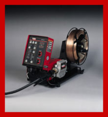
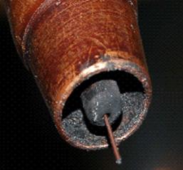
Lincoln STT Power Source, good for some root welds and not much else:
The two pictures show part of the Lincoln STT wire feeder and power source. I could be wrong but I believe Lincoln's price on the STT package with a few extras should be approx. $11,000 to $12,000.
Note: Lincoln advertises that on gage applications with STT you can eliminate weld spatter and reduce smoke.
The two, 300 amp traditional CV MIG equipment package as shown below that are available from Lincoln, Miller and others. These CV units sell with their wire feeders for approx $3500. Ref the Lincoln comment on STT and spatter on gage welds. With process control expertise, the majority of gage applications in the industrial world can be welded with controlled short circuit and produce SPATTER FREE welds utilizing the much lower cost, more durable CV MIG equipment (as shown in slow mo above). Also if you want pulsed on gage welds, in > 2006 and later years, you will be able to purchase much lower cost pulsed MIG equipment than the STT.
With a little MIG weld process control - best practice expertise, low cost CV equipment will get the job done to your satisfaction. Its up to you, if you have money to burn you know where the fire is. If you weld parts less than 0.080 and you simply cannot have miniscule weld spatter, then yes evaluate STT and the electronically modified short circuit weld transfer modes like RMD and CMT, with the low cost (< $4000) pulsed MIG equipment now sold by Miller (350P).
.
E.Mail Question:
Ed we run a Lincoln CV 600. We are running an 0.035 (1 mm) wire at 650 ipm and 28 - 30 volts. We use 90 argon 10 CO2 and are drawing about 200 amps. According to your books we should go into spray at >200 amps at > 420 inch/min, what's happening?
Ed's Answer. You have lost your current. If you note, on this power source you will find a process switch that can be set at three settings.
[1] UPPER SETTING: Stick SMAW,
[2] Middle SETTING SAW - CV,
[3] LOWER SETTING. Self shield (fcaw).
If you use the stick (SMAW) setting you will have selected a steeper slope which restricts the weld current. Use the SAW - CV setting and you should be drawing 240 - 250 amps, which is correct for that wire feed rate. Of course the power source could also require repair, or you may need to replace a fuse at your 3 - phase supply.
When a weld equipment manufacturer's rep informs you that their sophisticated MIG power source has "unlimited weld parameter adjustment potential", please remember first this is impossible and second this simply allows your workers to spend even more time "playing around" with typically useless, unnecessary weld parameters and controls".
AS MIG WELD EQUIPMENT BECOMES MORE SOPHISTICATED, THE POWER SOURCE MANUFACTURERS APPARENTLY DO NOT SEEM TO CONCERNED THAT THE WELDING EQUIPMENT IS ALSO BECOMING MORE COMPLEX, MORE COSTLY TO REPAIR AND LESS DURABLE..
E-mail question:
Ed. We have a Lincoln PowerWave and are having what Lincoln calls a "Birds Nest" problem. This is an intermittent problem but when they do occur, at various locations in the weld paths, they begin with an Arc 18 arc failure alarm, followed by the wire continuing to feed momentarily, doubling over on itself inside the weld gun conduit and jamming up the guide. We checked our lost arc detect interval in our weld system setup; it is set at the factory 0.25 sec.
First we replaced the wire feeder cable. Then we replaced the wire feed unit itself. Now they think we should have our Power Wave power source looked at, since the problem persists.
Ed dDo you have any suggestions on what can be causing this problem and how we should best deal with it? The snarls never used to happen;
it is a recent thing in the last couple of months. Sincerely. Brian O.
Ed's Answer.
For a weld power source that has more weld issues than an Enron balance sheet, you know what my answer to this problem would be. By the way if those that purchase weld equipment would spend less time talking to salesmen and more time on sites like this you would not have been having these problems.
The question today in 2015
Does the weld shop want a MIG power source that is electronically sensitive to many issues, or would the weld shop rather have a power source that is easily controlled and provides consistent weld performance.
FOR THOSE THAT ARE IMPRESSED WITH BELLS AND WHISTLES, LINCOLN MAY HAVE PRODUCED WITH THE POWERWAVE, THE ULTIMATE WELDGAME,SORRY POWER SOURCE.
As I write this in 2008, the Lincoln Power Wave is now one of the biggest selling robot power sources sold to the North American automotive industry. Most auto - truck plants believe that costly, sophisticated weld equipment with extensive bells and whistles will provide the solutions to their hands off management / engineering welding woes.
It's a pity the managers and engineers who selected this equipment, did not spend a few dollars and get a weld process control education. It will be even more of a pity the first time they see the frequent issues that the Power Wavet has generated and with the high repair costs it will require
~~~Lincoln Wave Forms: While on the subject of pulsed, let me quote from a Lincoln article on the Waveform in the Welding Journal, Jan 2000 edition. The Lincoln author states, "that the waveform in it's equipment is the means for determining the performance characteristic of a single molten droplet of electrode. The area under the waveform determines the amount of energy applied to that single drop. The Lincoln author continues with this statement which every weld shop decision maker has been holding his breath waiting for three decades to hear, "superimposed in a selective fashion over the waveform is the "adaptive" characteristic of synergic pulsed GMAW.
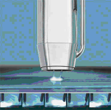
This 1980 picture is a slow motion shot of regular, "spatter free" MIG transfer in the glob to spray transition zone. Do you really believe that all the electronic sophistication mentioned is necessary for controlled drop - stream weld metal
transfer from the MIG wire tip to the weld?
Take any low cost MIG power source, built in the last 40 years, set it with spray parameters and watch it provide controlled, spatter free weld metal transfer.
Still not convinced? For god's sake, like the guy on the right, I could also take two car batteries and with the 24 volts create a power source to form a decent MIG weld on some welds. Also a point that many seem to forget. Most traditional >300 amp CV MIG power sources manufactured in the USA, from 1960 can produce a MIG or flux cored weld that would meet the most stringent weld code requirements anywhere in the industrial world.
~~PULSED WAVES UNDER THE BRIDGE~~.
It's Feb. 2004, I just spent a few days with a bridge builder. This company had two robot cells for welding bridge decks and frames. On the one side an ABB robot was utilized with Miller Delta Weld equipment, the other robot cell utilized Fanuc robots with the Lincoln Power Waves.
The robots and MIG equipment was purchased in the late 1990s. The steel, short length, 1/4 (6 mm) fillet welds made by the the Miller equipment required minimal weld repairs, and the weld repairs that were required were a usually a result of the part fit not from the weld process.
In contrast in the robot cell containing the Lincoln Power Wave, the MIG weld rework for two years had been over
[1] FANUC ROBOT ISSUE. The Fanuc cells were supplied with through arc weld tracking. Due to the inconsistency and poor performance of this equipment the bridge company had turned the arc tracking off. To compensate they made the welds much larger and longer than the weld spec called for.
[2] POWER WAVE ISSUE: When evaluating the Lincoln power source, I found the Power Wave weld current variation on a weld 2 inches long, varied from 170 amp to 300 amps, with the same welds you could also note a two volt weld variation. This parameter instability from the power source, has dramatically impacted what should have been a simple weld application. This application required through the arc weld tracking, however it's not logical to try to utilize through the arc weld tracking when the MIG power source cannot provide relatively stable weld voltage or current on an application with a constant wire stick out.
[3] POWER WAVE ISSUE: The crater control on this unit was very poor. The robot / Power Wave data did not start to react till more than a second was added and even then the crater welds with optimum weld data, at best would be described as erratic. On bridge welds, if you cannot control the weld craters you have to compensate and make the welds longer.
[4] POWER WAVE AND FANUC ROBOT ISSUE: The weld arc on time on the application in the Fanuc cell accounted for more than 85% of the total cycle time. Due to the lack of effective through arc tracking and unstable weld conditions twice the amount of weld required was used for the bridge platform welds. The bottom line this weld equipment has caused the bridge manufacturer to utilize three shifts to do work that could have been done in less than 2 shifts. To resolve the weld issue the bridge company will for its next robot installation make sure it has stable weld equipment (not from Lincoln) and the robot has an effective through the arc tracking unit.
E.Mail April 2005:
From. D.H. at GM Pontiac MI.
Ed we are a GM plant in MI. I have about 50 Fanuc Robots all using Lincoln Power Waves pulsed MIG equipment. We weld using an 0.045 (1.2 mm) silicon bronze wire and argon gas. The 0.045 wire feed rate is 240 inch/min with 24V.
The robot welds are made on galvanealed thin gage parts. The robots were purchased around 2001 and 2002. In the last 6 months some of the Power Waves have extensive burnt backs to the contact tip for no logical reason. The burn backs occur any where in the welds. We have changed liners, the guns and tips. We even changed the power source. The good Lincoln Power Wave power source we have would also start to do the same thing when placed in the cell where the burn backs occur. We have had all the experts in and got no help including Lincoln, what do you think? Dave
Ed's Answer.Dave. As you are using short circuit wire feed rate for the silicon bronze 045 wire it's a pity your organization did not purchase the much lower cost Lincoln CV 400, you would have saved around $250,000.00 and avoided these power source electronic problems. Also this problem is already delt with at this site.
[] I am amazed that Lincoln or Fanuc did not help you as this appears to be a power source issue, however I guess your 36 month warranty is up. Yes burn backs can occur frequently if wire restriction issues occur, as you changed the guns and tips and checked the weld wire feed ability, that should rule that out.[] Are you using an external volt sensing (VS) lead? if so check continuity.
[] If the volt sense lead is OK, its likely the power source is causing the issues. Disable the VS lead. I have found that artificial intelligence (looped electronic feed back of the weld data) with pulsed equipment can be unstable even with new pulsed equipment and that the instability can increase with the aging electronics, (especially once the 36 month warranty is up). This problem in my simple mind, is the power source technology is beyond the capability of the power source mfg. I believe to disable the VS, a jumper lead has to be moved in the power source, this is supposed to only take 10 minutes.
[] If disabling the VS did not work, then in the robot pendant disable both the arc start and wire burn back functions as these functions have been known to influence weld performance and produce erratic results. To displace this preset power source weld data use separate weld schedules at the arc starts / ends.
[] Arc start. Use one to two volts higher than weld volts.
[] Arc end. Use one to two volts less than weld volts.
[] Your 24 weld volts for this application also sounds too high. For short circuit an actual weld voltage (indicated on the power source volt meter of 16 to 19 volts would be typical. For pulsed around 22 volts.
[] If using a laptop provided weld schedule / program, change to a standard power source program. Try the 045 standard short circuit mode for steel / stainless. Its a pity your 36 month warranty is just up, what's that song? "when will they ever learn"
See Lincoln issues above, and thanks to Greg Smith at Marada for his contribution. Greg also had to go through many frustrating issues with his Lincoln Power Wave equipment.
THE NEXT TIME YOU WANT TO SPEND MONEY ON "WAVE FORMS" I WOULD MAKE SURE IT'S AT THE POOL OR BEACH.
I have had extensive experience with the Lincoln Power Wave on many robot applications. I would rather not repeat the experiences. My advice to anyone looking at a Power Wave, consider instead the $2000 to $4000 traditional Lincoln CV units and use the thousands of dollars saved for a cool vacation. If you need a power source to hook up to a robot unfortunately I believe that Lincoln does not offer a low cost CV unit with a seperate Interface panel, so you then have to take that leap into the Lincoln waves,
A PULSED WELD PICTURE IS WORTH AT LEAST A THOUSAND WORDS.
The next two picture are are two 3/16 (5mm) fillet welds I made on 1/4 (6mm) stainless steel. The welds were made with a Lincoln 300 Power MIG. This power source is single phase, pulsed MIG power source that retails around $3,700 . The Lincoln 300 power source has pre-scheduled pulsed programs for specific wire diameters. This MIG power source was purchased by a company that welds steel and stainless parts. The MIG wire is an 0.035 - 308L stainless wire. I set the 0.035 (1mm) wire feed at 550 ipm which should be an optimum pulsed wire feed rate. The power source provided the preset pulsed parameters. I simply had to set the trim weld voltage to attain the optimum arc length. The welds were untouched after welding. Take note of the pulsed weld appearance and also the heat affected zone.
Lincoln pulsed power source with pulsed mode switched on.
Lincoln pulsed power source with pulsed switched off.
.
Switch off the pulsed mode and this 3/16 stainless, traditional spray transfer fillet weld was made with the same power source, consumables and wire feed rate as the pulsed weld. As you can see the HAZ is similar, this weld had similar spatter and similar surface. My point is simple, there is nothing special about either of these two welds, however, why pay an additional $15,00.00 for something you don't need to weld steel or stainless parts? Why pay for something that adds to the weld complexity, something that is less durable and more costly to repair?
E-MAIL. Oct 2008: : Ed I recently bought a new Lincoln 350MP, for pulse welding 18 ga aluminum. At first my new unit performed OK then the problem started, while welding 18 gage, my weld would flare up the wire back into the nozzle. The machine is rated to weld 19 ga. I got the supplier to exchange my machine for another one, which has the same problem, it flares just as bad on 1/8th alum. I have a push-pull gun, and the wire feeds fine. I'm running the machine on 50ft multi-strand cable, two 50 amp breakers. My friend is going to help me check out the electricity. Lincoln and the supplier have been no help, I don't have a clue, and I don't know what to do. Adam
Ed's Reply:Adam as you are using a push pull gun with this multi-purpose, Lincoln pulsed on pulsed, chopper technology I rule out wire feed issues. The fact that you purchased a multi-purpose power source and, these units are rarely noted for optimum MIG performance especially at low end or high end parameter ranges.You are welding very thin gage that requiries low, stable pulsed parameters and Imn sure the 50 foot cable does not help. Your weld problem sounds like you don't have enough voltage and current available to sustain a consistent pulsed arc. Low, erratic pulsed parameters would cause the pulsed arc plasma to collapse causing the arc to wonder or occasionally flare. I have said many times at this site, that instead of being impressed with bells and whistles and the wave forms, chopper and pulsed on pulsed marketing verbage, check out the equipment, especially the recommended low and high end welding range. The bottom Line when the same problem occurs in two new power sources, you have an equipment design or part problem. This is Lincoln's problem, not yours. As they are not likely to recall the equipment, and you have wasted enough of your time on this issue, send the power source back. The Miller 350P appears to have a good pulsed low end, give it a try. Ed
WHEN YOU PURCHASE MIG EQUIPMENT BELLS AND WHISTLES, DON'T EXPECT REAL WORLD RESULTS:
Lets face it the biggest attribute about some of the Lincoln equipment, may be the marketing names applied to the specific options and weld transfer modes. Chopper, pulsed on pulse, wave forms, all sound impressive and I am sure help in the sale of the in the equipment. The real question is does the technology in question perform in a consistent stable manner and do the resulting weld transfer modes provide real world benefit for the application.
For a pulsed equipment manufacturer to show his pulsed technology is superior, we are going to hear some wonderful pulsed equipment gibberish presented in the next decade. In 2009, expect a tremendous amount of new marketing induced bovine fecal matter to be presented on how advanced electronics will further influence the pulsed weld droplet size, shape and energy etc.
Unfortunately in an industry that too frequently has to rely on sales brochures and weld sales expertise to resolve it's weld issues, there are many welding customers that are ready to believe the pulsed MIG equipment sales hype. Also lets face weld reality. Weld distributors have never made much profit selling Lincoln equipment, a product line which now appears to be available in just about every hardware store in North America. I believe the high price of the Power Wave is it's greatest feature, and that feature benefits Lincoln and it's weld distributors more than it will benefit most weld applications.
2003. Be very wary of the JAPANESE Motoman 350 MIG Power Source, it's a sad excuse for a a welding piece of equipment
If you use Motoman robots, it's unfortunate that you may have purchased the Japanese built 350 MIG equipment. If you want a poor to mediocre, inconsistent, welds this quipment will provide it.
At two separate locations during 2003 I have had issues with the Motoman equipment. In Aug. 2003 it was my unfortunate task to optimize a large welding cell that utilized Moto Man UP6 robots with the 350 welding equipment. One of the new power sources was so erratic it had to be replaced. On the remaining equipment I found inferior arc starting characteristics, inconsistent weld transfer and the required voltage range was excessive resulting in globular type transfer.Later in 2003 I assisted one auto supplier of thin parts with his numerous robot weld issues. The parts were 1.2 mm thick, the weld wire was 035 - 1 mm. The weld mode selected was short circuit. I noted again with the Motor Man MIG equipment that at the required low wire feed short circuit settings that the minimum stable weld voltage required from this equipment was 1 to 3 volts higher than that which would have been required with the traditional North American CV equipment.
The required, higher weld volts from this inferior Japanese MIG equipment caused ERRATIC "globular transfer" and the additional voltage provided higher weld energy which added to the "weld burn through potential" on the thin parts.
I have a question for thos of you that dont have a life and still reading. Do you believe that when you water your lawn the grass will be greener if the water is pulsed when it leaves the hose?
What is an issue for most welds is the weld energy delivered. The bottom line, pulsed can produce in some instances a lower energy open arc weld mode. Therefore to justify purchasing pulsed equipment look for a weld application that requires the heat concerns, such as clad welding or welding aluminum;
[a] Pulsed provides lower weld energy than traditional spray transfer. However if you are aware of all the wire feed and voltage settings that can produce spray transfer with the different wire diameters, you can often replicate the pulsed weld energy with spray transfer and a smaller diameter MIG wire.
[b] Pulsed can provide weld spatter levels to an absolute minimum. If spray transfer is set correctly the weld spatter amount will be minuscule.
[c] Pulsed is beneficial on alloy electrodes that typically provide poor weld transfer, electrodes such as alum bronze. A real pulsed benefit.
MIG equipment I Would Not Recommend.If you have a robot purchase in mind the following power sources are what I personally would not recommend in 2008.
[1] The Lincoln Power Wave. This welding unit "will often take you where you don't need to go, restrict you where you should not be restricted, and make you pay a price you don't need to pay. With this power source in your robot cell it would be wise to make sure you have a spare. For optimum manual or robot carbon / stainless MIG welds stick with the Lincoln CV 400 amp power source.
[2] The Lincoln Ideal ArcThis multi-purpose unit provides mediocre MIG performance.
[3] The Panasonic HM Units. <2004 units. If Panasonic thinks this is a solution to North American welding problems they should fire their so called Japanese welding experts. If you purchased Panasonic pulsed equipment before 2004 godhelpbless you.
[4] The ABB/ESAB Arcitec. Sold as a built in with ABB robots. This erratic, poor performance power source introduced in the nineties must have put Swedish weld manufacturing technology back two decades. For more information on this "unique" welding equipment you know where to find me, and I won't be in Stockholm.
[5] Miller Maxtron. It's hard to understand how a company with Miller's reputation would want to place this machine into any welding shop.
[6] Miller Invision. Inconsistent performance, sold before it was ready for weld shops.
.
[7] Thermal Arc MIG equipment. Erratic electronics and poor pulsed / spray arc characteristics at high / low data.
[8] Kemppi. I do not like the performance or durability of their MIG equipment.
BACK TO WELDING REALITY.
Spray Transfer can be so simple. With traditional CV MIG equipment, an argon mix and two simple weld parameter settings, you can produce weld droplets as shown in this video, or turn the wire feed rate up and create a weld stream at higher current and voltages. Its true that with spray transfer, the weld droplets are not "individually controlled" but who cares, as long as they transfer into the weld in a stable manner, inside a suitable plasma. And if you want more or less MIG energy from CV equipment,
[a] change the wire feed rate,
[b] change the welding voltage,
[c] change the wire size or type,
[d] use a different gas mix.
[e] change the wire stick out.
With open arc transfer such as pulsed MIG and spray transfer, its not that important on how the weld wire converts to molten metal, what is important is that the molten metal transfers in a consistent, stable manner. A CV MIG power source has had this capability since the nineteen sixties.
MOST MIG WELDS ON PARTS > 3 mm WILL PROVIDE MARGINALWELD FUSION:With correct spray weld parameters, the traditional spray transfer is stable and almost completely spatter free. Yes traditional spray transfer is hot, but as most MIG welds have marginal weld fusion this is a weld benefit not a weld detriment.
The primary issue with most spray welds is insufficient side wall fusion, there fore there is little logic to utilize pulsed and reduce the potential weld energy.
At the end of the day, the following may be the best justification why pulsed MIG will one day soon be the world's number one MIG welding process.
A welding distributor if lucky may make 10 to 20% on a traditional $3000, CV. MIG power source / wire feed equipment package. In contrast on that $6000 to $12,000 pulsed equipment package which produces no more weld productivity and no better weld quality on most steel welds, that additional profit will certainly be an incentive for both the weld equipment manufacturer and distributors. And lets face it, with the short pulsed equipment life, well that's just a bonus to the MIG equipment manufactures who repair and sell this equipment.
You have to have a sense of humor if you weld carbon - low alloy steels, and you spent more than $4000 on that Pulsed MIG power source.
Pulsed MIG Equipment & WELD Consumables
Comparisons, Evaluations Continued.
Next time you consider paying $6000 to $12000 for that pulsed MIG power source, keep in mind that sound MIG welds have been made with two car batteries and a wire feed gun. However no serious welder would want to use battery equipment for their MIG welds.
You can pay $12000 for a pulsed MIG power source, or with
process control - best practice expertise, produce the best possible MIG weld quality and productivity on all steels, low alloy steels and stainless applications..
CONSISTENT MIG QUALITY & MIG WIRE SELECTION:
BEFORE CONSIDERING THAT NEW MIG POWER SOURCE MAKE SURE YOU ORDER THE CORRECT MIG WIRE TYPE. IN NORTH AMERICA, FOR DECADES THE NUMBER ONE MIG WIRE CHOICE IN THE AUTO - TRUCK INDUSTRY HAS BEEN THE E70S-6 WIRE, AS WITH MOST MIG WELD DECISIONS IN THIS IMPORTANT INDUSTRY, THE E70S-6 WIRE HAS BEEN THE INCORRECT MIG WELD WIRE CHOICE.
MIG Wire Facts Without Sales Advice:
[] When using argon mixes and welding cold rolled sheet metals or steel plates which have the weld surface area ground or blasted clean, irrespective of what your friendly sales rep informs you, the E70S - 2 - 4 and E70S-6 wires provide no weld benefits. In contrast to the E70S-3 wire, the E70S - 2 - 4 - 6 wires typically can result in increased surface slag islands which the paint shop dislikes, and the increased silicon can make the welds to fluid increasing undercut potential. For three decades ny messgae to the auto industry is for gods sake at least order the correct MIG wire which by the way will not be made in Japan, China or S.America.
In contrast to the E70S-6 wires. for those robot welds on cold rolled and galvanealed, the E70S-3 wire provides superior weld pool control with less propensity for weld undercut and burn through, and less weld surface slag islands.
[] If manual or robot welding on clean parts and producing "multi-pass welds", the weld heat build up and it's influence on the weld fluidity needs consideration. The use of the E70S-3 wire improves weld puddle control for these welds and limits the silicon and manganese build up in the multi-weld passes. Using the E70S-3 wire also helps in keeping the inter-pass weld slag to a minimum. Best results for "multi-pass" carbon and low alloy steel welds comes from using an argon 8-10% CO2 mix with an E70S-3 wire.[] If welding on galvanized or aluminized, or any coated carbon steels use E70S-3. Avoid higher silicon wires like the
E70S-6 wires as the silicon / zinc oxide reactions can cause hot micro-cracking in the welds.
[] E70S-6 wires were designed for use with the more oxidizing straight CO2 gas. When the E70S-6 wire are used with the argon 15 - 20 % CO2, these wires can benefit spray welds on plate with mill scale. Mill scale has a higher melting temperature than the base steel, and if enough scale is present, sluggish welds will result. The sluggish welds will , impact the weld fusion and the scale will create porosity. That high energy argon gas mix helps to reduce the sluggishness and the increased Silicon in the E70S-6 MIG wire not only provides increased deoxidizers the silicon also provides an increase in the weld fluidity which can be a benefit or can cause undercut. If the mill scale is causing weld issues, consider eliminating the scale with grinding or shot blast before welding.
[] The E70S-6 wires also benefit MIG spray welds on plate with excess rust, as 70S-6 wires have additional de-oxidizers = oxide scavengers, however keep in mind that gas shielded, flux cored wires are preferred for applications that provide excess scale, rust or other contaminates.
MIG WIRE MANUFACTURES AND THOSE "OVERSEAS" MANUFACTURED MIG WIRES.
I was assisting a large weld manufacturing plant in S. Dakota. This company utilized robots and was a large user of Lincoln L50 and L56 wires, two USA manufactured MIG wires which I typically recommend for MIG carbon steel and low alloy steel applications. While at the plant, the manuafacturing manager who like many inexperienced manages was focussed on weld consumable costs instead of weld quality, deposition rates and arc on times. The manager asked if I would look at two different (lower cost) new MIG wires they were evaluating from Lincoln. One wire was the Lincoln Easy Feed wire and the other, the Lincoln Super Arc wire.
When I tested the new Lincoln Easy Feed wire on the robot, I noted that in contrast to the L50 - L56 wires, the Easy Feed wire was very "voltage sensitive". To maintain spray arc stability with the Easy Feed wire, I noted the weld voltage on the Lincoln power source had to be constantly changed and fine tuned. This voltage adjustment was on a robot application in which the wire stick and arc length out was constant. The weld voltage (arc stability) sensitivity was again noted using short circuit transfer with the Easy Feed wires. When wires are voltage sensitive it typically means inconsistent or poor wire chemistry and it means you simply cannot trust the weld wire manufacturer.
Also notable with the Easy Feed wire was the spray transfer weld plasma generated with this wire was narrower than normal and favored the center of the 6 mm fillet weld puddle with less control on the weld pool edges. The Easy Feed wire weld performance was a real contrast to the superior L50-56 wires which were noted for their arc consistency and a wider plasma coverage of the weld. A wider plasma provides greater coverage and control of the weld puddle surface. The narrower plasma resulting from the Easy Feed wire produced poor wetting of the weld edges, resulting sometimes in convex weld beads with scalloped edges. This factor increases potential for lack of weld fusion issues on specific applications.
IF THE CARBON STEEL MIG WIRE IS NOT MADE IN AMERICA DONT BUY IT. IF THE WELD WIRE DOES NOT PROVIDE YOU THE STABLE WELD RESULTS YOU DESIRE, ASK FOR A REFUND AND THEN CHANGE THE SUPPLIER FOR TREATING YOU WITH NO RESPECT.
I found that the Lincoln Easy Feed wires also were inconsistent in the slag island production. Sometimes on clean plate (ground with no mill scale) the Easy Feed S3 would produce much more surface slag islands than the Easy Feed S6. This slag result, was a surprise as there is supposed to be more slag producers in the S6 wire.
THE EXCESS SLAG IS THE E70S-3 WIRE WAS A DEAD GIVE AWAY THAT SOMEONE DOES NOT UNDERSTAND OR GIVE A DAM ABOUT THE CHEMISTRY LIMITS THAT SHOULD HAVE BEEN APPLIED TO MAKING THE WIRE.
By the way I carried out the Lincoln MIG wire test welds manually and with a robot. All the welds were made on ground clean plate using optimum weld parameters with fixed wire stick out in extremely controlled weld conditions.
As to the so called Linoln "Super Arc wire. I found nothing super about it. When I tested the Super Arc wire I found
it had similar weld traits to the Easy Feed wire. Both these wires were far inferior to the USA manufactured Lincoln
L50 - L56 wires.
SOMEONE MIGHT ASK WHY DOES LINCOLN WANT TO PALM OFF INFERIOR PRODUCTS OFF TO THE IT'S NORTH AMERICAN CUSTOMERS. IF YOU CANNOT FIGURE THAT OUT GIVE ME A CALL.
The questions that could come out of this Lincoln MIG weld wire test.
[1] Was the Easy Feed and the Super Arc the same wire in two different packages?
[2] Where were these poor MIG wire made and what was the Easy Feed wire and the Super Arc wire called before it was given the new Lincoln brand names?
[3] If a company has asked the weld distributor for a traditional Lincoln L50 or L56 wire, and that distributor provides them with the Easy Feed Lincoln product or any weld wire product that provides weld issues or is outside the AWS MIG wire specs, that weld shop has a perfect right to be upset and should consider legal action against both the wire supplier and wire manufacturer.
[4] Was Lincoln concerned about the inconsistencies or the consequences of the wire chemistry and the
silicon and manganese content of the wires under discussion?
[5] I have tested MIG weld wire for approx. 40 years. The once completely American made Lincoln L50 - 56 wires were for decades the best and most consistent MIG wires in North America and I am aware that the US plant that made these wires was often stretched to it's wire production limit. If you examine the side of the Lincoln MIG wire boxes or drums you are using, you may note that the MIG wires may have been produced in many third world locations around the globe. As a company that holds a USA monopoly position in the weld consumable market, it's obvious that Lincoln was not insisting of uniform global MIG wire manufacturing standards that were comparable with the L50 - L56 MIG wires it produced in the USA.
[6] In times when Mc Donalds gets sued because its coffee is too hot, should Lincoln customers who have more serious weld liability consequences and concerns expect the highest MIG wire quality standards from Lincoln, standards that at least are identical to the L50 - L56 products?
[7] Is the reality that Lincoln believes that the average MIG weld wire purchaser is simply not qualified to analyses MIG wire welding differences, so they can get away with selling chicken wire quality instead of
MIG wire?
[8] Should any weld shop have to waste time and money testing MIG weld wires that are causing weld issues? The company had to pay me for the day I spent testing the Lincoln MIG wires that did not perform in the way the company expected wires from a reputable USA wire producer. There was also the costs associated through the loss of robot weld production and the resulting weld clean up and repair issues.
Note. One of the great benefits of using a robot or automation with optimum MIG weld data, is the automation will quickly show the inconsistencies of a poor quality MIG wire.
Weld Question:
Ed, who makes the best carbon steel MIG wires in North America and why? I have tested and used numerous MIG wires from all over the world, and the Cleveland made Lincoln copper coated L50 (E70S-3) and L56 (E70S-6) wires that have been sold for
decades, are MIG weld consumables that can be considered optimum.
In North America. I also like ESAB (Linde products) for carbon stl wires, and Sanvik for alloys.
When you order a MIG wire from Lincoln, if you use pulsed or spray transfer and want their best product, don't order an E70S-3 or E70S-6 wire or one of their special Super BS wire deals, be specific, ask for an"L50 or the L56 wire; and while this industry likes to be guided by weld salesmen, don't let that sales rep sell you anything different.
As for the wire size. Irrespective of what a sales rep informs you, the best MIG wire diameter for short circuit and spray welds on parts 0.060 to 3/16 (1.6 to 5 mm) is the wire I have been recommending since the nineteen eighties, the 0.040" wire. If you cannot get the 0.040 wire the second choice is the 0.035 wire. For all pulsed welds use the 0.045 wires. And for all welds on parts over 1/4, and single pass fillets to 5/16, the first choice is the 0.045 wire. For large single pass horizontal 3/8 fillets with robots I would use a
1/16 metal cored wire.
If you are having problems with inconsistent welds at high speed > 30 IPM, and you have determined it's not caused by that inconsistent pulsed MIG equipment you just purchased, try a Lincoln L50 wire against the wire you are using for comparison.
Fishing for weld solutions. Salesmanship & MIG wires.
If you don't know how to control a MIG weld, its likely you will be looking for a weld crutch such as a unique MIG wire or magic three part gas mix.
If you read or hear or read BS like this;.
Try our new "Super MIG Arc Copper Coated wire"
Try our new "Super MIG Glide Bare Wire" (free of Copper coating).
Try our new "Micro Finish Premium MIG wire."
Try our new "P MIG wire" developed for your sophisticated pulsed equipment.
Try our new M3 wire. The MIG 3 wire was developed for three part gas mixes.
And you buy into the above crap, I would suggest you look to another industry for employment, possibly you should consider a career with McDonalds.
If you want to pay an unnecessary MIG wire premium, the marketing and sales teams from the MIG wire manufacturers and the never ending weld distributor sales reps will be glad to reel you in. Always remember with a length of chicken fence wire, a two part gas mix and two batteries, you can make a weld that's just as good quality as most stick welds.
As a weld pro, you should be less concerned with the advertising marketing adjectives that describes the new wonder steel MIG wires and three part gas mixes. When evaluation that wire, examine the arc stability and consistency with a MIG spray weld. If it's consistent with spray you know its consistent with pulsed. By the way its difficult to test a MIG wire in the pulsed MIG mode as the majority of pulsed MIG equipment does not provide stable - consistent pulsed droplet transfer.
Once you like the MIG weld transfer characteristic with the wire you use, keep your eye on the weld wire cast / helix with each batch of wires delivered, also check the way the wire is wound, the wire surface cleanliness and the quality of the spool (avoid wire spools as the damage to easy) the wire is wound on.
My first choice stainless MIG wires, Sandvik products.
My two choices for steel MIG wires, Lincoln L50 / ESAB E70S-3.
My first choice aluminum MIG wires Alotec.
The MIG wires I would rather not have to work with are products from National Standard and Hobart. With the Hobart wires I frequently found inconsistent wire chemistry (inconsistent arcs), excess helix. From NS. I did not like the excess weld fluidity in the spray welds due to the high level of deoxidizers they use even in the S3 wire, or the poor winding and poor wire weld splices.
Note: If you ever have to use self shielding flux cored wires from Lincoln or Hobart, its time you shut the weld shop and opened a burger stand.
Spray Transfer & MIG Wire Burn Backs to the Gun Tip.
Ed, I work at Monroe, we are one of the largest producers in North America of auto - truck Shocks. Each of our many robots weld on average 200 to 400 parts per-shift. At some plants we average 2 to 5 burn backs per robot per shift. The burn backs requires that we replace the MIG gun contact tips. As the robot down time and time required to rectify the problem takes on average 5 - 10 minutes per burn back, you can imagine the weld production consequences. What is the primary cause of this common robot problem? Also why does this not happen as frequently with our manual welders?
The most common reasons for carbon - stainless MIG wire burn-backs to the contact tip:
Wire burn backs due to the use of oversized MIG wires in which the weld current cannot be used in the spray mode, so the welds are made in the "globular mode". The excessive weld spatter globs block the contact tip orifice and restrict the wire.
Wire burn backs caused by the use of globular weld data at the robot weld start or weld end data. Wire burn backs caused at the robot " weld starts". At a weld start the wire may not have enough forward feed momentum caused by any number of causes.
Wire burn backs " during the weld". One common cause of burn-back during a weld is when the MIG wire is restricted in the liner, or the tip or from lack of sufficient wire tension from the drive rolls. Restricted gun liners or a robot axis issues in which the gun cable is twisted are a frequent robot causes for wire restriction. These problems frequently result in a wire burn back which can melt the end of the contact tip. These problems can occur at the arc start or during the a weld.
Robot Issue. When welding with a robot especially when using an 0.035 (1mm) wire, sometimes the robot arm over twists the gun cable restricting the wire. This is noted more with the small wire diameters and specifically when the burn back consistently occurs at a single weld location.
Why the common wire burn-back problem occurs.
Many factors other than wire feed issues can influence a wire burn back.
- Wire stick out length too long and the wire almost touches the part at the start. A wire burn back variable that can be adjusted on most equipment.
- Robot program, poor arc start data. Programmers will benefit from the data found in my books.
- Lack or insufficient shielding gas at the weld starts.
- Wire feed restrictions in liner, cables or tip.
- Weld parameters set in the globular mode.
The following weld data and much more is found in my books & training programs. Click here:
Wire Stick-Out (ESO) influence on burn-backs.
As the robot starts an arc, the robot control sends a signal to the power source to open the contactor to energize the wire. When the wire makes contact with the work, the wire feed should be feeding forward with full inertia. In all instances the electronics work quicker than the mechanical feed and the high start current available during the wire short circuit can melt the MIG weld wire before it can be fed forward at it's full speed.
Many robot personnel are not aware of the influence of their wire burn back data on weld start issues. They may set the "wire burn back" data in the weld program so the wire stick out is approximately 12 to 15 mm at the weld completion. As this long wire extension makes contact with the grounded work at the next weld, before the wire has a chance to be fed forward the weld current and voltage is delivered creating an explosive short circuit. The wire short circuit depending on the start voltage utilized can produce very high current causing the weld wire to disintegrate or melt back to the contact tip.
The MIG wire stick out at a weld completion is controlled by the "wire burn-back control data". The wire stick out at the weld completion should always be kept as short as possible. The wire burn back should be set so the wire stick out is approx. 5 - 6mm from the end of the nozzle. A normal nozzle to work distance should 1/2 to 3/4 (12 - 18 mm) depending on the welding circumstances. With spray transfer, the contact tip should be recessed inside the nozzle 2 to 4 mm.
Important. At a weld start there should be sufficient Wire to Work Distance, at least 3 - 6 mm to ensure the wire is feeding forward before the wire makes contact with the work.
DON'T BE THE WEAKEST LINK ON YOUR WELD TEAM, FOLLOW THIS LINK TO ED'S BEST WELD PRACTICES AND PROCESS CONTROLS.
Contact Tips Stick-Out. A few years ago thanks to the MIG process ignorance by MIG gun manufacturers, the standard robot MIG gun produced in North America had the contact tips located either flush with the end of the nozzle, or "sticking outside the nozzle"
BOTH OF THESE CONTACT TIP POSITIONS CAUSED NUMEROUS ROBOT WELD ISSUES.
The major MIG gun manufactures who delivered their robot guns with the contact tip sticking outside the gun nozzles simply did not know better, then again I suppose we should not expect MIG gun manufacturers to be aware of the fundamental weld process requirements, after all they still classify their automated MIG guns for use with straight CO2 when less than one percent of robot MIG welds are carried out with straight CO2.
Lets face it when it comes to MIG gun manufactures and process expertise they are no different than the companies who make MIG equipment, the robots and weld consumables. At most of the plants I visited that were using spray transfer on parts > 1/8, >3 mm, the robot MIG guns would be welding with the contact tip stuck outside the nozzle creating short wire stick outs and numerous contact tip issues would occur during the shifts. As the company rarely had shorter tips available, I would tell the people on the floor to cut 3 to 6 mm of the contact tips.
It does not take a rocket scientist to figure out that if you stick a MIG gun contact tip too close to that spray weld, that requires high weld parameters and produces high weld heat and spatter, you will increase the potential for contact tip issues. As for that pulsed weld, if the contact tip extends outside that nozzle that typically means less wire to work distance is available to create that unnecessary,y small weld drop and allow it to transfer across an arc gap without being in contact with both the wire tip and work.
Many factors influence arc start with robots, "electronic time" has extensive influence. All MIG robot programmers should be aware of the factors that effect arc starts, and aware of optimum start welding parameters of each available mode of transfer, for each wire diameter used. This data is in my books and robot process control training resources.
How many companies are aware that pulsed welding is much more prone to wire burn back then traditional MIG weld spray transfer.
The primary reason there is a contact tip concern with pulsed welding and robots, is with the pulsed process there is a time factor and arc length concern required to create and transfer the pulsed weld drop that provides no steel weld benefits. For a spatter free weld transfer the pulsed weld droplet has to keep to a minimum size, then cascade across an arc gap into the weld without contacting the wire tip and weld at the same time. If the pulsed weld drop makes contact with the work and wire at the same time an explosive short circuit in the pulsed weld drop will occur. The pulsed drop short circuit explosion will cause spatter and disrupting the controlled formation of the next weld drop which can effect the weld and fusion consistency. The pulsed mode requires a longer arc gap than that is necessary for spray transfer, two to three times the length. The longer arc gap means a shorter wire stick out from the end of the contact tip. The shorter wire stick out increases the potential for wire burn backs. Want a 100 pages of why pulsed can cause weld issues you won't get this data from Lincoln, Miller or ESAB, you will get it from my 600 page "Managers and Engineers Guide to MIG book"
You can not control a MIG weld using
a wore out contact tip bores like this.
How many manufacturing companies do you think will daily manual - robot MIG weld with contact tips in which the tip bore diameter is worn to twice the diameter of the MIG weld wire?This condition is typical and the solution is simple, start each day with a new TIP and if using high wire feed rates and long weld cycle times, start each shift with a new contact tip.
Robot Weld Travel Rates:
The robot or automated weld speed rates for fillet welds are obviously first determined by the weld size which influences the utilized weld deposition rate. Another restriction is the weld fusion requirements. Travel too fast with that robot and irrespective of the weld current or weld mode utilized you will have a weld fusion issue. The weld surface condition, the weld length and the shape of the steel (round components are more sensitive to lack of fusion than plate), will also influence the weld speed and weld fusion.
How fast does a manual welder weld? Typically manual MIG welds are made in the 8 to 30 in./min speed range.How fast does a robot weld? In contrast single wire robot MIG welds are made at typical weld travel rates from 10 to 60 ipm.
Note using my extended WSO techniques in My Management Engineers Guide To MIG book, I have attained robot weld speeds of over 80 inch/min.
Lets hope the Chrysler Shock welds are OK on your vehical.
Many years ago Monroe a major USA shock manufacturer requested my assistance as they could not get their robot spray welds on their shock bracket welds to qualify for a Chrysler weld - shock load test specification. Chrysler engineers required the bracket welds on the shocks absorb at least a 13,000 lb test load. After robot welding the steel brackets with 5 mm fillet welds on shocks that were only 2 to 3mm thick, Monroe found that the shocks bracket welds would fail prematurely, typically in the 7000 to 9000 lb range.
The Chrysler weld spec for the shock bracket welds required that the welded brackets should pass a test load of 13,000 lbs. It took me less than two days of manual welding and testing on the shock bracket welds to reveal that any test load of less than 19,000 lbs indicated lack of weld fusion in one of the four bracket welds.
There were three reasons the Monroe shocks could not meet the minimum shock weld test load requirements.
[1]The robot spray transfer welds were made on cold rolled round parts.
[2] The robot weld speeds were set too high.
[3] The robot weld lengths on the brackets "were to small.
After I figured out the weld problems, I changed the weld wire size to a smaller wire which increased the weld current density. I reset the spray parameters, extended the shock bracket weld length by another 3 mm. The shocks bracket weld than average a load test of 21,000 lbs. Visit the Robot Management section for many robot application issue stories.
HOW FAST SHOULD A ROBOT GO?
Many robots today are either welding too fast or too slow. It's not just the lack of weld process expertise or lack of information on robot weld speed potential that proliferates throughout this industry, a common problem is that the MIG wire size may be wrong, or maybe it's because pulsed, globular or short circuit is being utilized when spray would be superior. Maybe the weld issue is the part design, joint type, part thickness or ridiculous gaps many auto / truck companies present to the robot weld cell. Optimum weld speeds for all applications and weld compensation data for potential weld issues are covered in my books.
WHY PAY A PREMIUM FOR MIG EQUIPMENT?:
MIG equipment can be simple or complex and the low cost simple equipment can provide the same or superior weld results than the more costly complex equipment.
A complete 350 - 450 amp Pulsed MIG equipment package including the wire feed control is available in North America in the typical price range of $6000 to $12000. Where as a conventional CV unit in the same amp range would be approx $4000. What do you get for that $8000 difference?When selecting MIG equipment for the weld shop, the weld shop decision maker has many opportunities to throw good money out of the weld shop window and in the last three decades, thanks to process ignorance, hundreds of millions of dollars have been wasted on unnecessary, costly bells and whistles..
<2010: Pulsed MIG equipment has in the past two decades caused tremendous issues for shops that robot weld common carbon steel and stainless applications. For approx. 40 years I have been evaluating MIG equipment and after years of painful, slow pulsed equipment development, I have found two pulsed MIG power sources (mentioned later) that while they are not necessary for steel and stainless welds, however they can provide "limited" application weld benefits for some specific applications.
Note Pulsed MIG has always benefited the heat sensitive aluminum applications.
Most of the pulsed weld issues that are provided at this site are not with the logical pulsed mode of weld transfer. The pulsed issues are with the pulsed weld equipment manufactures who were responsible the following.
[a] Two decades of unqualified, exaggerated pulsed weld process hype that added to the global weld shop confusion.
[b] Providing faulty pulsed equipment to the welding market and providing no pulsed product recalls. The bottom line is numerous, global weld shops were left with erratic performing equipment that in many instances negatively affected both the weld quality and productivity.
[c] Weld equipment manufacturers who produced pulsed MIG equipment that is extremely costly to repair, equipment that rarely made it through it's product warranty period.
WHEN WE LEARN FROM THE WELDING PAST, WE CAN AVOID THE WELD MISTAKES AND
WELD COST CONSEQUENCES THAT WILL OCCUR IN THE FUTURE.
MILLER PULSED EQUIPMENT. THEIR "BOVINE FECAL MATTER" STARTED IN THE 1980s.
1980s. MILLER ELECTRIC. THE INTRODUCTION OF THE MILLER PULSEDSTAR MIG WELDING EQUIPMENT AND THE NORTH AMERICAN BIRTH PLACE OF PULSED BOVINE FECAL MATTER.
In the nineteen eighties, the largest technical college in Vancouver Canada purchased Miller's first pulsed MIG power source, the Miller "PulsedStar". This pulsed equipment cost the college approx. 400% more than a traditional CV. MIG power source.
The Vancouver technical college was exited about it's investment in new weld technology. For many weeks the instructors at the college tried to get the Miller pulsed power source to produce a simple vertical up fillet weld with an 0.045 (1.2mm) MIG steel wire on a 6 mm steel plate. All position MIG weld capability was one of the prime features touted by the pulsed MIG equipment manufacturers.
(Note: Vertical up welds were not attainable from regular MIG equipment using spray transfer).
As the weld process control training manager for Linde, (Union Carbide - PraxAir) Western Canada, I was considered an expert on the MIG process, I was also a strong advocate of Miller welding equipment. The Vancouver college asked if I would visit and see what I could do with their costly pulsed MIG package. I was exited to work with the so called new pulsed technology and scheduled a day to weld with the Miller PulsedStar.
I set that PulsedStar power source at every possible wire feed, voltage and pulsed frequency combination possible. The PulseStar simply could not provide a suitable wire feed / pulsed parameter combination to MIG weld a common "vertical up fillet"and to add insult to injury, the pulsed welds made in the flat and horizontal weld positions were vastly inferior to those made when the pulsed mode was switched off and the traditional spray transfer was utilized.
For many years after my introduction to the Pulsed Star I went around North America turning the pulsed mode off and teaching the disgruntled Miller customers how to set traditional spray and short circuit with this equipment.
It's important for the reader to note, that in the nineteen eighties, up to the development of pulsed MIG equipment, that without question Miller built some of the world's best MIG equipment.
The Miller Delta Weld product line, was for decades and still is my first choice for customers who want the world's best performing, traditional, CV, MIG equipment.
AFTER THE USELESS MILLER PULSEDSTAR, MILLER FOLLOWED WITH THE PULSED MAXTRON and this unstable pulsed MIG power source does not deserve one positive line in this web site.
WHO COULD ENVISION THE PROBLEMS WITH THE NEXT PULSED POWER SOURCE FROM MILLER, THE INADEQUATE MILLER INVISION:
After the Miller Maxtron which provided no cost or quality weld benefits for carbon steels or stainless welds, steel welds, Miller provided the pulsed Invision. This power source went through more E-Prom changes than I have had pints of Guinness.
And then the Miller Accupulse. If you used this equipment on robot steel / stainless applications using pulsed and the adaptive arc mode and you had the weld process expertise necessary to evaluate a weld arc / transfer, you may have noticed the arc instability, arc ignition issues, crater problems, arc outages or wire burn back issues to the contact tips.
Note: Many of the pulsed adaptive arc issues that Miller had on their <2004 equipment were similar issues they had on their pulsed equipment made a decade earlier.
July 30-2004. E Mail. Ed. Your pulsed MIG description of arc sensitivity with high speed welds is is exactly what I am experiencing with our robots and the new Miller Accu-Pulse process / Auto Axcess. Our new auto bumpers are thin gage, 1/16 1.6mm HSLA and martensite. I tried to weld above 40 IPM with the Accu-Pulse and could not do the weld due to weld skipping and arc instability. We went to an .035 1 mm wire and could not get the travel speeds. We changed to .045 1.2mm wire and had to run the pulsed arc with the arc length buried in the part, this resulted in extensive weld spatter also the part could not handle the pulsed weld heat and we would have holes all over the place. With the disappointing pulsed weld results we now use high end short circuit CV with the 045 wires and are attaining 40 IPM travel rates. I have no spatter on the part and have no arc stability problems with the short circuit. I hate to admit it but this is is another pulsed failure in my book and I wished we had read your book before purchasing this weld equipment. I could get these short circuit weld results from a CV power source for half the costs..
Regards G S.
2007 From Ed: Keep in mind for the last two decades, pulsed MIG equipment was typically sold to weld shops where traditional, low cost, none pulsed CV MIG equipment was utilized. The approx. $2000 - $3000 CV equipment provided great MIG and FCAW application potential, good arc stability and for many weld shops the CV equipment lasted ten to twenty years.
It's logical to wonder why the MIG equipment manufactures you are loyal to, do not seem to thoroughly test their pulsed MIG welding equipment before selling it their customers.
For those weld shops that purchased pulsed MIG equipment before 2005 and noted arc instability, weld end crater issues and wire burn back issues (especially on robot welds) and welds with short weld lengths, the MIG equipment manufacturers are not likely to compensate you for their poor performing, over priced MIG weld equipment. Rather than listening to a sales rep, It's beneficial that all weld decision makers be aware of the potential short falls and idiosyncrasies of the pulsed equipment purchased.
2003: MILLER - WHEELS AND PULSED MIG WELD DILEMMA. A USA tier one wheel supplier, asked that I analyze it's numerous automated MIG weld process issues. The management had purchased over 100 Miller Invision 11, Pulsed MIG units. The MIG weld equipment was required for the companies new robot lines and manual weld repair stations. After three months in production the shop found it had become impossible to produce consistent, MIG weld quality. There was welding chaos at the plant and the daily automated weld repair rate was over 60%.
The plant management and engineering team had no doubt what the cause of the welding problem was, they had placed the responsibility for their weld issues on the shoulders of their shop floor workers.
After evaluating the numerous weld issues, in my report I spelled out that the majority of weld faults were not caused by the automated equipment or by the workers. The weld issues predominately were caused by the Miller weld equipment.
It's a pity this tier one company management and engineers had minimal expertise in the equipment vital to their manufacturing These managers lackedMIG weld process control expertise. and did not understand the meaning of equipment ownership.
If the management had purchased Miller or Lincoln's "none pulsed" lower cost, more durable, CV MIG equipment, they would have saved the plant approx. $600,000,00 on the MIG equipment purchase and with a little MIG weld process expertise found in my process control training resources, the management could have got their daily weld repair rates to less than 5%.
2005: MILLER AND MORE PULSED MIG ISSUES.
In February 2005, I was asked to assist a Canadian, tier one, auto supplier with it's automated steel weld issues. The welds were made with the latest Miller Accupulse MIG equipment. Each part required two simple yet critical welds that were only 20 to 25 mm in length. When I examined the small welds two things stood out.
[1] Over 70% of the Accupulse "weld length" was a concave smooth surface resembling a crater rather than a weld.
[2] In the middle of each weld crater was a large pore and with many of the crater pores you could see without magnification one or two cracks propagating into the crater.
The large weld crater and weld pore was strictly a result of the Accupulse equipment. Irrespective of what weld data I placed into the ridiculous Miller palm pilot weld control, the results were the same, "a large crater with a large pore". I worked for more than 10 hours to get rid of the crater and pore issues however it was hopeless. Also there was no control for the MIG wire burn back and this function was automatically controlled by the power source. At the end of the day, I believe that the Accupulse power source delivered an excessive high voltage for the wire burn back and this voltage resulted in the crater defects.
The Miller Accupulse crater defects had gone on for months. Miller's response to the engineers at the auto company was that the equipment was still in the "Beta phase" (they seem to provide the Beta excuse for just about most MIG electronic power source they had built between 1980 and 2000). The Miller solution to the serious weld defects was at the end of the weld re-strike the arc. However due to limitations in the automated equipment and PLC controls there was no way to re-strike the arc. For 4 years, this Canadian auto company produced parts in which the small length welds had more crater than weld and the majority of the welds had cracks. Many of the parts welded would eventually lead to failure, however as they were only American car parts, nobody seemed to give a dam.
There could have been grave liability cost consequences for the weld issues generated at the plant. The apathetic weld management at the plant could have readily sued Miller. However to sue a company over weld issues, you need management and engineers who understand and can prove the root cause for their daily weld issues, and lets face it, you won't find many managers or engineers in the auto / truck industry that have this fundamental weld process expertise.Just to show you how long this BS has been going on take note of this email in 2013.
Jan 2103: Ed. We have had arc end weld issues with 2 Miller Auto Axcess 450 D.I's in a dual arm Motoman cell since the installation. It seems the Auto-Axcess Sharp-Start routine is causing small explosions at the weld ends. These explosions can be heard and seen as little balls of molten metal shoot out of the cell at the arc ends and some times cause micro crater cracks little "snowman" looking eruptions that have to be ground off and manually repaired. We needed assistance se we called in the Miller rep.
When the regional Miller rep came to our plant he first blamed the weld wire. Then he blamed the gas mix, the gas flow rate, the weld voltage, wire feed speed and the wire stick-out. He then blamed the raw materials we were welding and then followed with we should change all the weld schedules from DC Spray Mig to AccuPulse. With nothing working for this joker, he finally he decided that thee smooth drive rolls on the metal-cored wire was the problem. More to the point, I asked repeatedly if he could turn off the Sharp-Start and auto burnback "features" he said we would have to talk with the Miller Engineer responsible for the Auto Axcess line.
Do you know what we need to do to disable these "special features" so I can use normal crater fill and burnback techniques? By the way we weld only 3/4" Hot-Rolled plate and its a railroad application. All the robot welds are in the 2F position, 3/8" single pass fillet.
The gas and voltage lets us burn through the mill scale pretty well and we have used these parameters for years in manual welding with regular CV equipment.
Our weld data is as follows.
Wire: Select-Arc Select 70C6 .062.
WFS: 330 IPM.
Voltage: 28.5.
Gas: 80Ar/20Co2.
Flow Rate: 40 - 50 CFH.
Wire Stick-Out: 3/4 - 7/8
Travel Speed: 40 cm/min
Thanks In Advance. Jeff Christensen. Mfg. Eng. Progress Rail Services.
2003 - 2004. Ford (Quality is Job 1) F-150 Truck Frames.
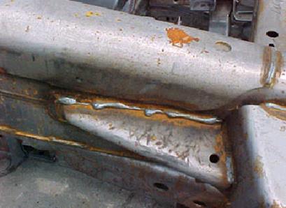
A Condensed Pulsed MIG Weld Report on the Ford F-150 Frames.
It's the intention of this report to deal with the root causes of the numerous robot / manual weld issues found on the Ford F-150 Frame truck robot line.
At this time your robot frame weld productivity is only 50% of your goal and your weld repair personnel report that the majority of the MIG welded robot frames require rework. Of the 140 robot welds on the frame typically 60 to 80 of these welds require manual weld rework. Of the sectioned critical welds that daily require macro examination of the weld fusion, an average of 20 to 30% of the welds revealed lack of weld fusion. As the photo below indicates, many of the robot / manual weld repairs are poor quality. The numerous manual weld repairs are providing a patched product which provide both poor weld integrity and a poor visual weld appearance.
The general Ford management / engineering lack of weld process control expertise at the plant along with the poor selection of the Miller Invision equipment and innapropriate size weld consumables are daily negatively impacting your robot weld productivity and quality potential. To find out the rest of the Frame Weld story click here
You need to melt the wire tip, you can do it the hard costly way with pulsed MIG,
or do it the eay way with much lower cost, CV MIG equipment.
HOW POOR PULSED WELD CHARACTERISTICS DELIVERED FROM POOR ELECTRONIC PULSED MIG EQUIPMENT NFLUENCED MY CAREER:IN DEALING WITH STEEL MIG WELD APPLICATIONS, I MUST HAVE SPENT ALMOST THREE DECADES GOING FROM ONE WELD SHOP TO ANOTHER, TURNING OFF THE USELESS, ERRATIC PULSED PARAMETERS THAT WERE IMPOSED ON THE STEEL WELDS AND SWITCHING THE EQUIPMENT BACK TO THE TRADITIONAL, CV, STABLE SHORT CIRCUIT OR SPRAY MODES.
Its 2010 and I am still switching Miller / Panasonic pulsed equipment and Lincoln Power Waves back to the CV modes to improve the customers weld performance
SO HOW IS THE MIG EQUIPMENT IN YOUR WELD SHOP?
[] Are your weld equipment purchases influenced by inexperienced purchasing managers, sales advice or by the unqualified weld shop personal preferences, rather than by weld application considerations and weld transfer mode and process logic?
[] Did you purchase Japanese MIG welding equipment on the belief that the Japanese can produce excellent electronic equipment. When the weld reality was the designers of the Japanese pulsed MIG equipment obviously knew little about weld requirements, arc characteristics, weld transfer modes and weld application requirements.
[] Is your weld shop immersed in a culture and weld shop myths that restrict the ability to make rational weld equipment decisions?
[] Do your weld decision makers look regulary to a biased weld salesmen and respond to glossy, weld equipment brochure promises that rarely deliver.
[] Does your weld shop have eight different MIG weld power sources, seven different MIG and flux cored wire types and and six different gas mixes. This is always an indication of lack of weld process expertise?
[] Are you still wondering why you paid three hundred percent more for that pulsed equipment and the weld improvements achieved are marginal?
MIG Welding equipment. Why pay more than you have to?
I have been evaluating MIG equipment for approx. four decades. I have established optimum MIG welds in more than a thousand companies in a dozen countries. I have never had a problem attaining optimum manual or automated weld quality and productivity with traditional, low cost, CV MIG equipment utilized on carbon steel and stainless welds.
Before 1990, the best, traditional CV MIG welding equipment in the world was manufactured and built in the USA by three companies,
[1] Linde. (Union Carbide).
[2] Miller.
[3] Hobart.
For those of you that think I forgot Lincoln, some of the pre 1990 Lincoln MIG equipment that I evaluated, I believe was on par with the substandard MIG equipment you would typically find today, manufactured in some third world country.
Welding Steel Plate and Rational Weld Equipment Selection:
The Miller "PipePro"
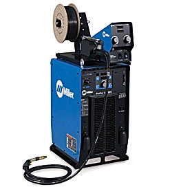
Was at this time approx. $11000 with FEEDER.
LOOKING FOR THAT MIG EQUIPMENT SUITED TO PIPE WELDS?
If you weld pipe you know that sometimes you will want to weld with SMAW, MIG, FCAW, and GTAW. Miller states that when it comes to pipe welds, the PipePro does it all. The real question, is the PipePro necessary and does not it consistently provide 5G code quality welds on any wall thickness and with all common pipe alloys?.
MILLER PipePro Plus: The PipePro is a multi-purpose MIG power source that offers RMD (Regulated Metal Deposition). The RMD mode is the only unique transfer mode on this costly package. RMD is a modified short circuit process. The bottom line is the RMD process lowers the short circuit current (lowers short circuits per second) available for a given short circuit wire feed rate, and RMD also offers dynamic puddle control which provides dubious real world weld benefits.
MILLER RMD ROOT WELD Note: If you rotate your pipe joints there are no advantages from the RMD process in contrast to traditional short circuit transfer attained from much lower cost CV MIG equipment. The RMD mode is primarily advantageous welding in the 5G position especially at the in the the 5 to 7 o'clock over head position. However in contrast to TIG and TIP TIG the RMD process cannot handle many of the root and pipe alignment changes that are common in pipe shops.
MILLER PIPEPRO PULSED MIG FOR PIPE FILL PASSES . The PipePro has a MIG pulsed program that is supposed to be suited to all position pipe fill passes, however be aware that the pulsed mode of weld transfer will with specific applications and alloys (sluggish) provide lack of weld fusion and porosity issues. The bottom line, with the majority of pipe applications, the pulsed MIG mode has always delivered a poor ratio of weld energy to the weld mass delivered and the weld speeds that result. On most code quality pipe welds, the pulsed MIG process will never compete with the TIP TIG process
2007: MILLER PIPEPRO NEGATIVE: ELECTRONIC INSTABILITY AND MILLER'S INABILITY TO TEST IT'S PRODUCTS BEFORE BRINGING THEM TO THE WELDING MARKET:
When testing the PIPEPRO on 5G fill passes I did see some pulsed arc instability and there were soft ware problems on the unit I tested which ironically was at a Miller product center in Atlanta. Miller has been consistent in bringing electronic equipment to weld shops without adequate, controlled field weld tests. In 2011 and many pipe shops have tested this equipments and after x-rays lack confidence in the pulsed mode.
If you are using pulsed MIG on specific 5G welds with wall thickness > 8mm and welding with specific (common sluggish alloys) there will be concern for lack of fusion and if you rotate your pipe you dont need RMD, regular short circuit for the root can be just as effective with spray for the fill passes.
ANOTHER PIPEPRO NEGATIVE THE PALM PILOT: The equipment I tested, had soft ware issues and we did not have a ridiculous palm pilot to view or change the weld data. When I did get to try the palm pilot I found it a complete waste of my time. I believe this type of useless electronics has no place in a weld shop, however I can understand how bells and whistles like this make more profits for Miller.
PIPEPRO POSITIVE: SIMPLE TO SET: High marks to Miller for simple operation and actually focussing on the pipe weld applications. The PipePro also provided pipe settings for both Argon - 2% CO2- and argon - 15%CO2 gas mixes and for the 0.040 steel MIG wires.
Note to Miller: While at AGA and Airgas I developed and introduced the argon 2% and 15% CO2 MIG gas mixes for the North American market over 20 years ago. As for the 0.040 wire, I am the only person in north America that has AGGRESSIVELY promoted this wire size since the 1980s. Well done Miller management for using my suggestions. Its a pity you did not send me a Hallmark card of thanks with a small renumeration enclosed.
2011 CODE QUALITY WELDS: THERE IS ONLY ONE WAY TO ENSURE NO WELD REWORK WHEN WELDING IN ANY WELD POSITION, ANY ALLOY, ANY WALL THICKNESS, VISIT THE TIP TIG SECTION.
TIP TIG in contrast to TIG is a process that enables much higher wire feed rates and increased weld current that result in faster weld speeds & much lower weld heat input.
T IP TIG has a unique patented wire feeder that agitates the weld pool improving weld fusion (especially beneficial for sluggish duplex and stainless alloys) and dramatically reduces weld pore defects.
This TIP TIG pipe weld was made by a Westinghouse. The weld is being made with TIG wire feed rates 250 - 280 inch/min with deposition rates on par with flux cored and pulsed MIG. On this weld the welder achieved a wire feed 250 - 300 % greater than any manual TIG welder could achieve, with a weld quality higher than that attained by any regular TIG welder.
Note: Companies such as Exon, Westinghouse and WSI (Aquilex) lead the way in the USA developing 5G, TIP TIG pipe procedures with manual wire feed rates 250 - 300 % greater than that attained by regular manual TIG welders.
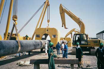
CONSIDERING PURCHASING THAT MEDIOCRE
"MULTI-PROCESS" MIG POWER SOURCE?
As MIG and FCAW account for approx. 85% of the welds carried out in weld shops, is it logical to pay an unnecessary high price for CC/CV multi-process equipment?
Are you considering a none pulsed or pulsed, multi-process MIG unit that enables MIG / SMAW / TIG / FCAW / ARC GOUGING.The majority of these power sources are used by companies who's MIG welders rarely utilize the multi-process capability.
Please note, In contrast to traditional CV MIG equipment you can pay approx. $1000 to $2500 extra for the multi-process equipment that typically provides poor to mediocre MIG / FCAW performance.
A logical approach for a weld shop that is looking to purchase a number of multi-process MIG CC/CV units is to purchase the lower cost, standard CV 350 - 450 amp equipment. Then purchase a single CC unit capable of TIG / SMAW / Arc gouging. The CC unit can be mounted on wheels and readily transported around the shop when needed. Remember when your welders are welding with the regular TIG and SMAW process, your company typically is not producing cost affective welds.
For those of you interested in MIG / FCAW weld process optimization, you may want to note that the typical slope output from a multi-process, CC/CV power source is typically steeper, (for a given wire feed rate delivers less current less fusion) than the slope output of a traditional of a regular CV power source.
The bottom line with many CC/CV machines. For a given wire feed rate, you simply don't get the typical amount of weld current delivered by a good CV unit, and with these wire stick out sensitive process you can end up with LESS WELD FUSION and more porosity especially on steels and alloy steel applications > 5 mm thick.
[] Are you having robot or manual weld issues that affect your weld quality productivity or down time?
[] Are you ready to purchase weld equipment, gases or consumables and would rather not waste your money?,
[] Do you want the best method or procedure for a specific MIG / FCAW / SAW / PLASMA / GTAW application?
Check out my best weld practices and process control resources at this site and for TIP TIG info visit www.tiptigusa.com.
ED'S MANUAL AND ROBOT WELD
PROCESS CONTROL RESOURCES.
ED OPTIMIZED ROBOT WELDS FOR HUNDREDS OF COMPANIES. A FEW OF HIS PROJECTS, FORD F 150 FRAMES - VOLVO CABS - CORVETTE FRAMES- HARLEY BIKE FRAMES - NEW BEETLE CAR SEATS - THE ROBOT WELDS ON THE WORLD'S LARGEST CATERPILLAR TRUCKS.
Ed's weld resources solved weld quality - productivity issues on these products.
MILLERMATIC 350P:
My first evaluation of the 350 indicated that the pulsed characteristic were reasonable to decent on this new power source. As it was from Miller who were not known for outstanding electronic MIG equipment, it made me wonder where Miller got this pulsed electronic technology from and the price was excellant.
Update 350 P. Dec 2008: After comparing this power source with other pulsed equipment, this power source unlike the other pulsed equipment developed by MILLER and it actually provides good pulsed characteristics for none pipe welds. Also its good for short circuit and spray welds on carbon steels, stainless. However when it was introduced, it provided poor to mediocre pulsed MIG weld transfer characteristics for aluminum welds. Note: Most of this power source pulsed weld benefits are minor and typically derived on some gage steel / stainless parts 2 - 4 mm.
FOR THE LAST TWO DECADES, MY PULSED MIG POWER SOURCE CHOICE:
THE OTC-DAIHEN PULSED MIG POWER SOURCE:
I RARELY REQUIRE PULSED HOWEVER IF THE CUSTOMER WANTS TO SPEND EXTRA FOR THE PULSED EQUIPEMNT THIS WAS AND STILL IS MY FIRST CHOICE FOR ROBOT PULSED WELDS AND FOR MANUAL STEELS - STAINLESS AND ALLOY WELDS. IF PURCHASING A PULSED POWER SOURCE FOR NONE CODE WELDS & MY CRITERIA WAS:
[a] "CONSISTENT" PULSED TRANSFER FOR THE DATA PROVIDED.
[b] EXCELLENT PRE-ESTABLISHED PULSED WELD SCHEDULES.
[c] THE NEED TO MAKE PULSED PARAMETER ADJUSTMENTS FOR UNIQUE WELD APPLICATIONS SUCH HEAT SENSITIVE PARTS OR FOR CLADDING WITH HIGH ALLOY WELD WIRES SUCH STAINLESS OR INCONEL.
|
[d] THE NEED FOR "DURABLE COST EFFECTIVE PULSED MIG EQUIPMENT".
1980- 2010: THREE DECADES OF SO CALLED MIG EQUIPMENT EVOLUTION:
< 2010. The worst MIG equipment found in the industrial world was typically found in Japan and Europe. Thanks to companies like Miller, Linde and Hobart, for decades the USA could claim the world's best CV MIG equipment. However during the last decade, thanks to the common process ignorance found throughout the North American auto / truck industry, Japanese MIG equipment became common with too many Big Three and Tier suppliers. While Japan can claim the world's best cars, from a welding perspective, Japan's claim to welding fame during the last two decades was that it produced most of the world's "worst quality MIG welds".
AS THEY WERE NOT CAPABLE WITH THE EQUIPMENT - CONSUMABLES THEY MADE, JAPANESE BEST MANUFACTURING PRACTICES RARELY INCLUDED MIG WELDING, THIS WAS TRUE IN 1983, AND ITS STILL REALITY IN MANY JAPANESE AUTO / TRUCK PLANTS 2015..
One reason for the bad welds in Japan. In contrast to North America, Japan had few industrial air separation plants. Without access to reasonably priced argon and argon mixes, Japan was stuck with CO2 as its primary MIG welding gas. The CO2 would of course not produce spray transfer. This weld gas also provides a limited short circuit weld parameter range. If you want to weld parts with traditional MIG equipment and those parts are > 1.8 mm, the 180 plus amps with straight CO2 produces erratic "globular transfer."
For decades in Japan you carried out this practice. First you MIG weld the parts, then you grind off the poor weld profiles and excessive weld spatter. Hopefully you are all aware of the negative aspects of the "globular weld transfer" from the highly reactive CO2 MIG process.
The CO2 weld transfer mode at weld currents above 180 amps produces erratic weld transfer, fusion concerns and extensive weld spatter. Globular transfer can also occur with argon mixes and poor weld parameters.
As MIG weld robots evolved in Japan in the 1980s and the British did development work on the pulsed process, the Japanese weld industry had minimal experience with the world's most popular spray transfer weld mode. Japan with its domination in robotics addressed the lack of argon gas in its country and it's poor CO2 MIG weld quality by developing sophisticated electronics for its manual and robot MIG welding equipment. The weld results from this equipment in the eighties and in 2007, were and still are rarely ideal.
The ironic logic. When the USA MIG equipment manufacturers saw the Japanese robots and erratic Japanese pulsed power sources selling well to the Japanese auto manufactures in North America, many US companies who lacked "weld process fundamentals expertise and believed that anything to do with manufacturing from Japan must be first class, quickly got on the weld train and purchased from Panasonic and Motoman, erratic, poor performing, sensitive, costly MIG equipment .
Note: Many auto/ truck plants in North America daily weld with erratic globular weld transfer, the reason has nothing to do with the weld equipment, the reasons are the general management and engineering lack of weld process expertise, incorrect wire size selection, and inappropriate weld parameters.
Panasonic MIG Equipment Issues
and their lack of weld process expertise:
Ed. The company I visited welds 6xxx series, extruded aluminum, thin gage parts. They had purchased a Panasonic VR OOGAL 11robot, with a Panasonic 350 amp Panastar RA 350 pulsed power source. For the welds they used an 0.046, 4043 wire and argon. The MIG wire spool was mounted on top of the robot, and they used a regular four-drive roll feeder with a water-cooled gun.The problem robot welds were short lengths, 5/8 to ¾ long. The robot welds are made on aluminum square tubes 0.070 thick. The 6xxx tubes are welded to a thicker alum part 3/16 thick. Since they purchased the robot the completed welds never look consistent over their short lengths. All the thin tube welds were made with the same weld data, yet in the same locations on the parts, some welds look fluid while other welds look cold. Most of the welds ended up with a black and dirty appearance yet the push gun angle is correct. These welds caused so many issues the company was ready to give up the robot and go back to manual TIG. For the rest of the story, click here.
Instead of an "AI" UNIT I would have called this
an Stupid Power Source, SPS unit.
2007. ARTIFICIAL INTELIGENCE MIG POWER SOURCEs TYPICALLY MEANS ARTIFICIAL STUPID EQUIPMENT. I cringe every time I am asked to resolve Panasonic MIG weld equipment issues and that request comes too often. I cringe because the problems are often with the equipment and unless you change the equipment you don't completely resolve the issues.
Typically the individuals who purchased and use weld equipment from companies like Panasonic and Motoman simply lack the weld process expertise necessary to make a judgment on the weld equipment . It's my belief that the Panasonic MIG equipment I had to work with was likely developed by electronic engineers who may have had more expertise in designing CD players or TVs than with the development of MIG welding equipment. Its hopeful that in 2011 improvements have been made then again then again maybe not.
THE WELD INDUSTRY BOTTOM LINE. OVER PRICED, MEDIOCRE PRODUCTS THAT PROVIDE LESS THAN OPTIMUM WELD PERFORMANCE WILL ALWAYS HAVE A PLACE WITH WELDING CONSUMERS THAT LACK WELD PROCESS AND APPLICATION EXPERTISE.
In the one hand, we have had North American manufacturing envy for DUBIOUS Japanese weld manufacturing practices and an unbridled admiration for any Japanese electronic equipment.In the other hand, we have the North American weld equipment manufactures realization that the electronic chips, bells and whistles in MIG welding equipment create a gravy train in which they can charge ridiculous prices for pulsed MIG weld equipment. Combine both hands with an apathetic weld industry that is too frequently attached by an umbilical cord to a weld equipment supplier and you can understand why many companies end up with overpriced weld equipment that causes many weld issues.

BEFORE YOU WASTE YOUR DOLLARS ON PULSED MIG EQUIPMENT FOR WELDING CARBON STEELS TAKE A LOOK AT THE NEXT PICTURE:MIG welding 1/4 (6 mm) fillet welds at a weld deposition rate of 13 lb/hr. On the left we have a pulsed weld made with a $12.000 pulsed power source. On the right, a spray transfer weld made with $3000 traditional CV power source. Both welds were made with the same 0.045 1.2 mm wire feed rate, using an argon - 10% CO2 gas.
Carefully examine the two welds below,
I know which one you choose.
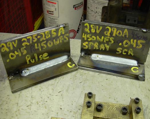
It's understandable that a global industry that lacks fundamental weld process control expertise could be influenced to purchase useless, costly, inconsistent pulsed MIG equipment for its steel / stainless robot weld applications. What is difficult to understand is when you see companies like John Deere and Caterpillar buying into the same useless electronic bells and whistles.
After more than four decades of evaluating MIG equipment and more than two decades of watching failure after failure of Japanese and European E-proms, microchips and circuit boards, I have come to the following conclusion which I am sure many of you will disagree with.
2007. When MIG welding carbon steel, none pipe applications > 4 mm, I have yet to find a measurable, practical, cost effective weld benefit from the overpriced Japanese, European or USA Lincoln / Miller Pulsed MIG equipment. In reality the pulsed arc plasma profile and stability is inferior to the traditional MIG spray transfer mode for many common MIG applications.
It seems that when it comes to MIG welding steels, weld shops from Michigan to Georgia, from Dakota to Louisiana, from California to Florida are prepared to pay $7000 to $13,000 for a pulsed MIG power source to weld carbon steel and common alloy steel applications. The weld reality is that the majority of the welds produced could be made at the same or superior quality and productivity with process expertise and a CV power source you could purchase for around $3000.
This low cost, single phase, 250 amp, multipurpose (MIG - TIG - STICK) power supply made by ESAB can when welding steel applications outperform many sophisticated, electronic MIG power sources sold by ESAB and other weld equipment manufacturers.
E Mail to Ed 01/ 05.
Ed I have a 220 amp stick welder which I love and am looking for a recommended MIG welder (either 220 or 110) to use in my home shop for steel frames trailers etc. There are so many products out there and a lot of crap too - but I want to invest in something durable that gives me good range to weld various thickness. I'm told that flux-core material allows me to penetrate a bit thicker but have an Argon tank and could go that way too.
Any direction you could provide would be appreciated.
Regards,
Chris Escobar.
Ed's Answer.
Chris, any traditional Lincoln. Miller or ESAB CV power source AS SHOWN IN THE PICTURE ABOVE will do the job. Consider either a single or three phase unit as they will surpass your needs. Try and get a power source that provides at least 250 amps at 60 % duty cycle. (Spray transfer with an 0.035 (1 mm) steel wire will come in around 180 to 200 amps and an 0.035 or 0.045 gas shielded flux cored wire can weld almost any application in the 120 to 250 amp range. Purchasing a power source with a built in wire feeder is logical.
QUESTION: Ed I believe you need different guide rolls for different MIG wire types what's recommended. JH. Manchester UK.?
Ed's Answer:
[] For solid hard wires use a "smooth VEE groove" built for the wire OD.
[] For flux core wires use a vee groove with at least on roll providing a serrated surface to improve the grip. Be careful you do not apply too much drive roll pressure to these wires.
[] For aluminum wires a U groove with smooth surface again don't use excess drive roll pressure. With aluminum ensure minimum gaps between the inlet, drive rolls and outlet guides to avoid buckling.
A WELD EQUIPMENT REALITY:
Irrespective of the weld quality or code requirements, irrespective of what the weld sales rep or equipment manufacturers tell the welding industry, ninety percent of all manual and robot, (none pipe) carbon steel / MIG welds "do not benefit" from costly, sophisticated, electronic pulsed MIG equipment.
However ninety percent of all welding equipment manufacturers and distributors do appreciate the additional revenue and profits generated from the sale of the pulsed or electronic MIG is equipment.
Dear Ed. I am welding engineer and I live and work in Bulgaria. I want congratulate on your WEB site. I found it 5 days ago and I can`t stop reading it, well done.
Krassimir PANAYOTOV
E-MAIL panaya@abv.bg
Practical MIG Gun Advice: Water cooled guns are used for many robot installations while the weld reality is lower cost, easier to maintain air cooled MIG guns would work just as well and reduce both maintenance and down time. If your robot weld application utilizes < 260 amps, and the weld lengths are short and the arc on time is moderate, consider a 400 to 600 amp air cooled gun.
Both Tregaskiss and Binzel make excellent robot / manual MIG guns. I try to avoid Bernard or Lincoln guns even when given one free with the purchase of a power source.
Weld Gun Contact Tips. I believe that many of the contact tips sold today in North America are made in countries that have very low labor costs and very little concern for maintaining the tip bore dimensions as provided by the original tip design.
During the last decade, I have seen a dramatic decrease in the quality of weld consumables. It's very common today to find 0.035 and 0.045 tips that have undersize bores, add this issue to the common, poor quality over size weld wire and you have found another reason why you are having erratic weld results, burn backs and bird nests at the drive rolls.
Spray / Pulsed Transfer and Contact Tips. With high weld current applications, ensure the spray contact tip is recessed 1/8 to 1/4 (3 - 6 mm) inside the gun nozzle. The higher the current get closer to the 1/4 recess.
Recessing the contact tip extends the contact tip life as less spatter and heat will get onto the tip. The recessed tip provides a longer MIG wire extension which can reduce the high weld current that will result from high wire feed rates. The weld current reduction can assist in weld puddle control and a longer wire stick out reduces wire burn back potential. Also with spray transfer consider the purchase of heavy duty, wider nozzles for your guns.
Short Circuit and Contact Tips. For applications that use less than 180 amps, stick the contact tip outside the nozzle about 3 mm. The tip outside the nozzle allows the use of the lowest possible voltages. Also the benefits of a short wire stick out adds to arc stability with low current applications. For short circuit or globular transfer have the contact tip flush with the nozzle.
CONTACT TIP SIZES:
Ed, I recently purchased your "A Management and Engineers Guide to MIG Welding". The book is everything I had hoped it would be...and then some!
The company I work for has a handful of welding engineers scattered throughout North America. Over the past few months I have had a growing number express satisfaction with using 0.030 tips with 0.035 wire. My issue is this, no one has given me a specific engineering or scientific reason for the tip change. Simply, "So-and-so told me to try it. It works for him so I do it to." (I believe the original idea came from a suggestion from a weld sales rep.) This concerns me. I foresee a number of problems including increased uneven tip wear, restricted wire feed, spatter blockage issues, etc., and I don't see where current flow would be influenced significantly.
Am I missing something?
Ps: Thank-you for having the motivation and courage to make this kind of information available. I have not yet come across an opinion that I did not share or a concept I did not admire.
Regards. Fraser Rock. Welding Eng:
Ed's Reply: Fraser: Thanks for kind words. I have found in many plants that a common issue like this is usually a distraction or crutch for plant people who frequently lack the ability to get to the real root cause of their daily weld issues. Most tip issues typically result from burn backs, poor start and end data, incorrect wire stick outs or wire helix issues.
A contact tip needs to be approx. 0.007 to 0.010 larger than the MAX wire diam. Keep in mind the wire will expand slightly during welding. When you purchase smaller tips than those recommended , remember that with today's inconsistent weld wire quality the weld wire OD is frequently on the plus side.
If robot operators or weld personnel manually run the wire through the tip and it snags, the wire is too large or the tip is too small. If the wire is manually fed through the tip and makes consistent contact its fine. If the tip bore is not the correct size, (check with drill gauge), change your tip manufacturer. If the wire OD is too big, change the wire manufacturer and for god's sake get rid of weld distributor that provides you with poor quality products and provides bad advice. There is the possibility is the tips you purchase are made in China or Timbuktu. There are many quality issues with off shore, substandard weld consumables. Good luck. Ed:
2005: NORTH AMERICAN LAMENT.
If its not just the politicians screwing this country, its the bloody Chinease.
MIG Wire Feeders and "Dual Weld Schedules".
Without question one of the greatest benefits derived on manual MIG wire feeder is the ability of the welder while welding to flick a switch or trigger on the MIG gun and go back and forth between two separate weld schedules.
Dual schedule wire feeders have been around for at least two decades, (Linde DigiMig was one of the first). As with many other practical weld products, the global weld industry has been slow to differentiate from the useless bells and whistles and purchase real world practical equipment such as dual schedule wire feeders.
Two great tools a welding company can use to optimize their manual steel or stainless
MIG welds;
[1] Provide employees with effective "weld process control training".
[2] Provide the MIG bells and whistles on the "wire feed controls". such as "two preset, pre-approved" weld schedules.
Today in Ford, GM, Chrysler, Japanese auto plants and tier one suppliers, we will see manual weld repairs being made on the robot made welds with pulsed MIG equipment. The repair welders will typically use only one weld setting to fill weld burn-through holes or place welds on top of welds on parts from 1 to 6 mm. The correct equipment of choice for manual MIG weld repairs is a low cost 250 - 300 amp CV power source. Use an 0.035 (1mm) wire for the weld repairs and it's logical to use a dual schedule MIG wire feeder that with a flick of the switch would give the repair welder either a low current short circuit weld and higher current spray setting. Of course if your company was really on the ball, you would provide those repair welders with MIG process CONTROL training as found in my self-teaching MIG process control books, click here.
The "dual weld schedule" MIG wire feed control, is one of the most practical pieces of MIG equipment that has been available for two decades, that's why the auto industry and most weld shops have shown little interest in it.
You can spend $8,000 to $12,000 and purchase the worlds most sophisticated pulsed MIG power source for your shop. You would then have to invest another $2000 - $4000 for a wire feed control. However if you really want to get consistent, optimum MIG quality and productivity, purchase a low cost, < $3000, 350 - 450 amp Miller, ESAB or Lincoln power source, then invest another $2500 on a dual schedule wire feed control.
WAVE FORMS? WHILE SOME WELD EQUIPMENT MANUFACTURERS WILL TELL YOU ABOUT THE MILLIONS OF WAVE FORM ADJUSTMENT ON THEIR SO CALLED UNIQUE MIG EQUIPMENT, BE AWAE THAT ALL IT TAKES TO MAKE ANY WELD IS FOUR SIMPLE WELD SETTINGS:
WELD SCHEDULES? WELD EQUIPMENT MANUFACTURER MAY WISH TO PROMOTE THEIR COSTLY MIG POWER SOURCE WITH 90 WELD SCHEDULES. HOWEVER WHEN YOU USE THE WELD PROCESS INFORMATION AVAILABLE IN ED'S BOOKS, YOU WILL LEARN THAT ONLY FOUR SIMPLE WIRE FEED AND VOLT SETTINGS ARE REQUIRED FOR A GIVEN DIAMETER ELECTRODE TO WELD ANY STEEL / STAINLESS APPLICATION.
Once the weld decision maker has purchased that dual schedule wire feed control and decides on two optimum settings for the manual welders in his shop, all that is required is to dial the two settings into the dual schedule wire feed control, turn a key on the control and the two optimum set of weld parameters are locked in.
Both Lincoln and Miller offer dual schedule wire feed units priced $2,000 - $3000. Both these units are a good choice and are logical with a 300 - 450 amp, traditional CV power source. From my perspective the dual schedule feeder control and conventional CV equipment is a much more cost effective and , practical approach to MIG and flux cored welding, rather than purchasing a costly poor performing Inverter or a pulsed power source that offers limited benefits for most steel and stainless welds.
WARNING: Give careful consideration to the effectiveness, position and durability of the dual schedule MIG "gun switches" found on many MIG guns, it appears making a quality, durable, dual schedule MIG gun switch is a big deal to many MIG gun manufacturers.
That new, pulsed MIG power source may provide four million wave ~~forms~~, however please note, costly "artificial, electronic weld equipment intelligence" can never compete with human weld process intelligence. That's the process intelligence that is available in my MIG weld process control books and Training CDs. There are only four weld settings for any MIG or flux cored wire, if you work in the weld industry its beneficial if you know these settings. Do you know those settings?
Weld Equipment Bells and Whistles keep getting more ridiculous yet weld shops keep buying them.
I was staggered at the AWS weld show to find one MIG weld equipment manufacture providing a "remote control" for the MIG power source. The control is similar to the one you use for your TV.
I can imagine a situation where the weld supervisor asks the welder why he is hanging around and not welding? The welder replies, “he cannot find the remote".
For more than a decade, Japanese robot and MIG power source manufacturers get the first prize for;
[a] unnecessary robot weld program complexity,
[b] poor robot / MIG power source communications,
[c] ridiculous electronic options in weld equipment.
It's a pity North American MIG equipment manufacturers are working hard to keep up.
Useless BELLS and WHISTLES.
Spain 2008. Above, Ed finds out what a stupid waste of time it is to have to set useless wave forms with the poor performing Miller Axcess with its Palm Pilot.
USA 2015: Its 2015, in contrast to the lower cost, more durable Miller CV >350 amp CV unit that will cost approx. 50% less, we have the Miller Axcess evolution and its called The Continuum. With this so called advanced pulsed MIG unit, we have yet another Miller power source that could not provide me any real world weld benefits for the vast majority of steels, low alloy steels and stainless welds,
Don't waste money on bells and whistles, use these process control self teaching / training resources that cost $300, and instead of wasting money on that >$7000 advanced MIG power source, you can save $3000 and attain the same weld quality and productivity.
EXTENSIVE PULSED MIG EQUIPMENT EVALUATION DATA IN SECTION TWO:
Ed'd Choice: MIG Weld Wires.

My BEST MIG WIRE CHOICES;
BEST MIG WIRES FOR ALUMINUM WELDS. Alcoa.
BEST MIG WIRES FOR STAINLESS. Sanvik.
BEST STAINLESS FLUX CORED WIRES . Kobelco / Alloy Rods (ESAB)
BEST CARBON STEEL FLUX CORED WIRES, (ALL POSITION) ARGON / CO2 MIXES. For the best gas shielded, flux cored wires, I have always recommended Alloy Rods, "Ultra sold by ESAB" Tri Mark products sold by Hobart and Kobelco products. I have never recommended Lincoln Electric gas shielded flux cored products as I found the ones I tested had many issues.
In contrast to the Alloy rod or Tri Mark wires, the Lincoln E71T-1 gas shielded wires I tested provide a smaller optimum weld parameter range, instability with the arc, and too many worm tracks. The bottom line the Lincoln wires were provided less weld deposition rate potential and the last time I tried these wires, the vertical up welds had so much porosity and worm tracks in the weld it looked like a cheese grate.
BEST CARBON STEEL FLUX CORED WIRES (ALL POSITION) USING STRAIGHT CO2.
My first choice, Kobelco.
Self shielded flux cored wires. These products do not belong indoors and so far only the inexperienced auto / truck industry has pushed their use. Any company that uses these products for indoor weld applications is not concerned about weld quality, productivity or the health of their workers.
BEST STEEL MIG WIRE. My first choice of carbon steel MIG wire is still the Lincoln L- 50 wire manufactured in Cleveland. However it seems today that some Lincoln MIG wires are produced in strange places like China or Timbuctoo. If you purchase Lincoln products that are not Cleveland manufactured, for robot SPRAY OR PULSED applications you may find the arc sounds change every few seconds. My second choice of MIG wire is ESAB 70S-3
THE WORST MIG WIRES: While providing process improvements across the USA and Canada, the carbon steel MIG wires I had the most robot weld issues with were made by Hobart, (inconsistent chemistry). I also had extensive problems with National Standard MIG wires which had too many cast or helix, and silicon issues, and their E70S-6 wire provided too much weld fluidity (excess silicon) leading to undercut on some applications and burn through on thin gage welds.
2004 National Standard MIG wires and the PULSED MIG weld BOVINE FECAL matter was really flowing.
I was amazed to read an advertisement in the Nov. 2003 Weld Journal from National Standard for the new N-S Pulse PLUS steel weld wire. NS claims that with their MIG wire and the pulsed process you will get less spatter , less fumes and reduce the need for grinding. NS claims that there pulsed wire is supposed to have a wider operating range.
I guess that $12000, useless pulsed power source you just purchased that's loaded down with electronic bells and whistles to control the arc now has nothing to do with the pulsed weld ability. This type of ridiculous product advertising is what adds to the mountains of Bovine fecal matter that has helped destroy the technical credibility of toady's welding industry. It's a shame a reputable magazine like the Weld Journal, a magazine that represents the American Weld Society allowed this form of advertising.
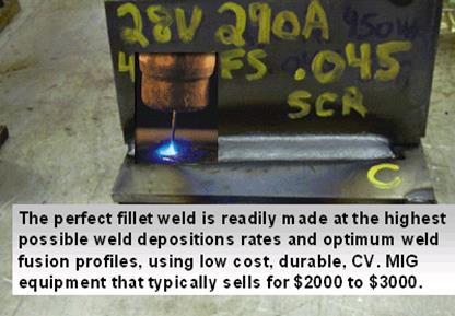
ED MADE THIS SPRAY 5/16 FILLET WELD WITH A E70S-3 MIG WIRE, A TWO PART GAS MIX,
AND A MIG POWER SOURCE AND WIRE FEED UNIT THAT SOLD FOR LESS THAN $3000
E Mail Nov 04. Ed. I spent 33 years with Esab India Ltd, selling MIG, TIG and Plasma equipment. Your web site is a wonderful observation of the global weld industry and how the pulsed MIG weld equipment manufacturers have for decades fooled the so called weld industry experts.
T.K.Bandyopadhyay.
FroniusTwin Wire a WASTE of time and money in 2004:
While the twin MIG wire process claims unique real world benefits from pipe welding to high speed automotive. Keep in mind two torches and two robots can also do what the twin wire process can achieve.
The Fronius Twin process shown above is a "tandem" welding process. This is one of the most sophisticated twin wire systems available. With the Fronius equipment there are two digital pulsed power sources working together. The Fronius Twin Digital machines produces a separate arc. A synchronization unit regulates the interplay of the two arcs. Too see the Fronius Tandem process on pipe, click.
Please note nine years later this process which I criticized for its poor performance in 2004 is today in 2013 almost none existent. That’s less useless bells and whistles for this sad industry.
MANAGERS BEFORE YOU CONSIDER COMPLEX AND SOPHISTICATED WELD EQUIPMENT LIKE THE TWIN WIRE PROCESS, IT'S FIRST LOGICAL TO OPTIMIZE THE EXISTING PROCESSES YOU ALREADY OWN.
When using the "single wire" MIG process, how many managers encourage their weld team members to evaluate the robot weld program, the process, the consumables, the parts, the design or the weld fixture to ensure they have done everything possible to attained the highest potential weld efficiency and deposition rate from their existing robots?
Irrespective of the weld equipment purchased, you cannot optimize robot welds without weld best practice and weld process control expertise.
For those managers, engineers and technicians that are prepared to read and involve themselves in the MIG process, please note, there are many things that can be done to greatly increase the traditional, single MIG wire, robot weld travel rates. This unique information along with robot weld process control information is available in my "Management Engineers MIG Book".
ELECTRONIC, WELD DATA MONITORING EQUIPMENT
CAN ONLY REPORT WHAT IT READS.
THE FOLLOWING IS A WELD PARAMETER GRAPH TAKEN FROM A MONITORING DEVICE USED ON A PANASONIC PULSED POWER SOURCE WHILE WELDING. THE CURRENT LINE IS BLACK THE VOLTAGE LINE IS RED. THE WIRE FEED AND WIRE STICKOUT WAS CONSTANT. NOTE THE LARGE CURRENT HIGH AND LOW SPIKES. NOTE HOW THE VOLTAGE DROPS TO ALMOST ZERO NUMEROUS TIMES. THIS ERRATIC WELD RESULT WAS ALSO TYPICAL FROM THE PULSED MODES WITH THE LINCOLN POWER WAVE AND MILLER INVISION.
Not a good weld parameter graph.
THE LOWER GRAPH SHOWS THE SAME WELD WIRE AND WIRE FEED RATE AS USED WITH THE PANASONIC EQUIPMENT SET AT THE SAME WIRE FEED RATE. THIS WELD PARAMETER GRAPH IS FROM AN "UNSOPHISTICATED" MILLER DELTA WELD WHICH COSTS CONSIDERABLY LESS.
NOTE THE FAR GREATER ARC STABILITY WITH BOTH THE WELD CURRENT (BLACK) AND VOLTAGE (RED). THIS STABILITY AND SUPERIOR OUT PUT FOR CONTROL OVER WELD FUSION COMES FROM THE MUCH LOWER COST, TRADITIONAL NORTH AMERICAN CV POWER SOURCE.
FOR THOSE OF YOU THAT GET FRUSTRATED WITH THE WELD PERFORMANCE FROM YOUR SOPHISTICATED ELECTRONIC MIG EQUIPMENT, ESPECIALLY ON HIGH WELD SPEED APPLICATIONS . NOW YOU KNOW WHY.
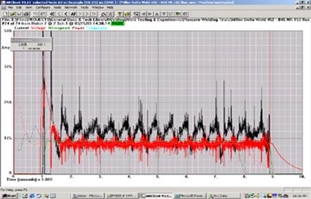
A good weld parameter graph.
WELD REALITY: FOR MIG AND FLUX CORED WELD STEEL AND STAINLESS WELDS MADE IN THE FLAT AND HORIZONTAL POSITIONS, A MILLER OR LINCOLN TRADITIONAL, 300 - 450 AMP CV MIG POWER SOURCE CAN OUT PERFORM ANY ELECTRONIC POWER SOURCE TODAY SOLD IN NORTH AMERICA.
Its the little things you look at in a weld evaluation.
With the Lincoln power source I found that the best way to attain stable, high speed steel welds was to switch the pulsed mode off.
The Weld Journal reports on Lincoln Electric F355i
Lincoln Electric's F355i pulsed power source communicates directly to the robot controller through an "Ethernet system". This eliminates some of the intermediary hardware and software usually required between the power source and controller and according to Lincoln, makes the entire system operate faster.
What the Weld Journal does not report is when I used this equipment I found that the Lincoln pulsed power source provided high speed pulsed welds that were extremely arc length sensitive. This sensitivity made the equipment's pulsed mode unsuitable for many high speed robot weld applications.
A few years ago, you could purchase a Miller "electrical interface" for the robot and power source. With correct consumables and weld data communication speed was not an issue. When something went wrong with this electrical equipment any electrician could quickly identify where the problem was and then repair it. I could duplicate any weld made today by the state of the art, Lincoln "Ethernet system" with equipment developed two decades ago. I know I cannot hold back the tide of fecal matter that is now flowing through weld shops however I can point out what is BS, and products that provide no real world weld benefits. If you have to ask a salesman or weld equipment rep about MIG equipment, be prepared for product bias and a great amount of exaggeration.If you don't see through the bovine fecal matter that has surrounded the pulsed equipment, you may want to start to teach your weld personnel Latin so they can pronounce the marketing names that will be describing the future weld equipment bells and whistles.
The weld process fecal matter continues. The Weld Journal reports. "The Panasonic Factory Automation's soon-to-be introduced B1 power source features a "32-bit RISC microcomputer" that gives it a level of intelligence more sophisticated than most welding robots and its data will run 125 times faster. The result is the use of inverter technology for waveform control of short-circuit GMAW.
Ed's comments. The graph on the RIGHT is taken from a Panasonic power source made in 2003. This oscilloscope volt amp graph was taken by a frustrated engineer at a Canadian automotive weld facility. He wondered why his costly, electronic MIG equipment provided inconsistent weld results.
The electronic pulsed MIG equipment may be advertised as "intelligent", however someone needs to show the MIG equipment manufactures that weld parameter, (volt-amp) stability is one of the most important functions of a MIG power source. After evaluating the so called intelligent power sources for almost two decades, I have yet to see one that can provide practical, cost effective, measurable welding benefits.
One could ask why make a power source more intelligent than the robot? The robot pendant should clearly spell out the weld data and time commands and the power source should simply respond. We don't need MIG weld equipment that "thinks" we need equipment that responds.
The bottom line is weld equipment manufacturers have yet to figure out the necessary electronic communication relationship between a robot and a power source. The weld equipment manufacturers seem do their thing and the robots manufacturers do theirs. It often all adds up to unnecessary electronics in the robot cells.
Weld Journal reports. Thermal Arc is shifting from the use of teach pendants to controlling the power source using a personal computer as with the Power Master 500P. "We see this as something we'll be doing more of," Wiseman said. "You can do more with a PC than with a pendant." To make it easy for the customer to use, the company made sure there was "nothing unfamiliar about the software" he said. "It looks like a normal Windows screen."
Ed's comments. Are these people REAL, for five decades this industry has struggled with two simple MIG controls, now they are talking about using a computer. Give a weld decision maker a conventional MIG power source and with three simple parameter settings per wire diameter, as shown in my books and training CDs, and that person will instantly set optimum MIG weld quality and productivity on any application in North America. The last thing any weld shop needs is a computer.
Weld Journal reports. ESAB has begun introducing machines with a special "switching technology" a technology that produces efficiencies similar to inverters but at a cost more like conventional power supplies, Fernicola said. In addition, the company's new Aristo MIG 400 model power source utilizes a "BUS system" that enables the power source and wire feeder to communicate in much the same way as an automobile's computer communicates with the rest of the car's systems.
Ed's comments. Does this mean we can drive it?
You hopefully are now getting the big BS picture about MIG weld equipment. In the weld equipment game of one up-manship. Each of these weld equipment manufacturing companies looks like it's dedicated to adding unnecessary costs and complexity to the welding industry.
E Mail to Ed 02/ 05. Ed. I absolutely love the website, it’s fantastic and has a lot of advanced
information that a professional welder like me loves to read. I have been working at Bobcat for the last seven years making the excavators and attachments for the skid steers. My plant in located in Bismark, North Dakota. This is a multimillion dollar plant that invests heavily in Fanuc robots, lasers, and anything else that is the latest craze. I really took note on your section about pulsed MIG.
Six years ago, I was working in the cab/canopy cell. We had three shifts, four jigs and could always stay ahead of the weld production schedule. There were approximately 10 people that worked in that cell on all shifts. For a few years we used the CV Miller Deltaweld 451 machines. One day I came in and found that half of our Miller power sources were replaced with small Panasonic Inverter pulsed machines.
The sales rep who bought in the Panasonic equipment told everybody just starting my shift that these were demo machines and go ahead and use them and tell him how they worked out a week later. The first problem was nobody knew how to set them up to weld. After playing around we figured them out. Even when set right they would spit and sputter during the welds, then they would go from a controllable weld to a weld that was way too hot.
My weld production went from one canopy per hour to 6 in 8 hrs. Try like hell I just could not get back up to the weld production I had attained with the CV miller equipment. At the end of the week we had 9 people out of 10 saying take these S.O.B.'s out. they SUCK! The sales rep response "we need to train you guys how to set them so we will all have a class". They never provided the class and we got stuck with equipment.
Six months later we get another visit from the Panasonic salesman, you would think this guy was running the weld shop. This time the sale rep was pushing the new Panasonic HM 500. At this time I started to get into the robot side of Bobcat. I was working in a cell that had a fanuc RJ2 and Miller 451 power source. It was nice MIG weld operation, STRAIGHTFORWARD AND LOGICAL with minimum weld issues, however but it wasn't meant to last.
The engineers in our plant replaced all the robot cell weld equipment with the Panasonic HM 500's. Because of the way our robot cells were setup, we had 1000 pound spools of wire on the outside of the cell and the wire would have to be fed through 60 feet of conduit to get to the wire feeder. With the miller equipment in the robot cells there was no problems, because of how their drive roll setup was designed. (four interlocking gear meshed rollers). The first thing that happened with the new Panasonic equipment was extensive burn back to the tips because of the how their feeder was designed. (one drive roller and then an idler). Again the problems generated was "our fault", yet we were told we need to learn how to use the Panasonic equipment. To get the Panasonic equipment feeding the wire in a more controlled manner, we had to reconfigure the cells so the weld wire was closer to the robots. Once closer to the robots the weld heat must have affected the Panasonic equipment as on average they seemed to burn up every 4 months! We actually had one power source that burnt up within 30 minutes after it was installed. About the time that Bobcat was ready to pull out, somebody leaked to our friendly sales rep that we were going testing both Lincoln and a new Miller model. The rep came back and told us that we should wait on changing over because Panasonic was releasing their HM 500 II machine and that they were much better machines. The salesroom gave the usual BS and demonstrate a machine to management that had more had more control than the cock pit in an airplane. There was of course an extra price to pay for the extra knobs but our gullible management again bought into the sales pitch.
Bobcat used to like to keep its weld equipment for at least 15 years before theychanged them out. We had the Panasonic equipment for less than 48 months when the management decided it had to go. I am back to welding with the Miller 451 and making some pretty sweet weld beads. I absolutely love welding but when you get people that come in and they don't know what they are talking about, it makes a McD's job start to look pretty good. Ed your website is great and I look forward to soaking up more knowledge from it. Best regards and thanks for your time to read this novel.
Note from Ed. This e-mail had it all. Lack of process expertise from both management and engineers. Lack of equipment ownership from management. The consequences from weld sales influence. Frustrated weld personnel. Overpriced pulsed MIG equipment and an industry that looks to useless bells and whistles as a crutch for its lack of weld process expertise.
MIG Contact Tip MIG weld Question.
Ed MIG contact tip issues is a prime cause of robot down time at our plant. We make steel auto / truck shock components. I figure we are losing over one hour of robot production per- robot due to the contact tip issues. I have read about special alloy tips and their influence on tip longevity and seen different tip profiles. My question is should we be doing more work on tip evaluation?
Signed. Frustrated robot weld tech.
Ed's reply.
Thanks to different alloy additions to copper of course some contact tips will offer different properties that can affect wear or conductivity. The shape of the tip is rarely relevant, thicker is typically just a little better than thinner. The real issue in most weld shops that utilize arc welding robots is to first recognize the process root cause of the contact tip failures. The vast majority of contact tips require replacement due to the following;
[a] Wire burn back due to poor robot weld start / end data.
[b] Use of oversized MIG wires causing the use of globular weld transfer.
Those large globular droplets quickly block the contact tip bore and create difficult to remove spatter.
[c] Spatter caused by poor weld parameters.
[d] Wire cast or helix issues.
[e] Tip in wrong position or nozzle to close to weld.
[f] Pulsed or spray parameters that create a short wire stick out.
The resolutions to eliminating all major contact tip problems are spelled out in my robot process control training resources, click here
Contact Tip Facts. Copper has been the material of choice for many decades, primarily because, after silver, it displays the second best electrical conductivity amongst all metals. Due to its face centered cube crystalline structure, pure copper is naturally ductile. Copper for contact tips is strengthened by a number of strengthening mechanisms including cold work, solid solution, precipitation hardening and dispersion strengthening.
The most popular and inexpensive copper alloy used in North America for contact tips is CDA C12200 P deoxidized copper). Precipitation hardening alloys such as C18100 (Cu-Cr-Zr), C18200 (Cu-Cr), C17510 (Cu-Be) have been common for high performing tips since generally they tend to have higher physical wear performance than C12200. Unfortunately, as most strengthening mechanisms, precipitation-hardening can compromise the electrical conductivity of copper. Plant experience with these alloys has been mixed; however keep in mind most plants do not correctly analyze the root cause of the tip problems and even fewer plants will take the logical process corrective actions. I found good tip data at www.finn-tips.com/copper-alloy-tips.htm. The bottom line if you are having contact tip problems the problems are typically not with the tips.
Dec 2009: E-Mail:
Dear Ed. I read your article on pulsed MIG and multi - process power sources about 12 months ago and agree with you entirely that they are far too complex and the advantages ( if any ) are minimal,
The sophisticated electronics with their inbuilt sensitivities have no place in a welding shop environment . The company I work for recently fell for the old sales trick and bought a Kempii Synergic Mig with all the bells and whistles to go with it ( tractor, tracks etc. ) all costing about
Au $30,000.00.
The Kempii power source is rated at 100% at 400 amps with a water-cooled gun. As far as I'm concerned this weld equipment is the most cantankerous, unreliable bucket of crap that ever had electrons shoveled through it . Although the gun is water - cooled the tips are prone to overheat and jam . The only way I've been able to overcome this is to use a 1.2 mm tips with 1 mm wire . The pulse parameters are so useless they border on farcical, maybe they were designed by an electronic committee at Kemmpi, certainly not by anybody with a bit of basic process knowledg about welding. This machine will do nothing that I cannot achieve with 400 amp CV machine and Standard Tweco gun and tips. I 've been the the game for 35 years and been doing coded welding for 30 of those years, but I have never seen such a complete waste of money or resources .
P.S We have a minor political party over here called the Democrat (no relation to the US guys ) and their motto is " Keep the bastards honest " . Ed I hope you continue to do what you do to keep the weld industry honest!
Craig Fourro Brisbane , Australia.
Make sure your hunting dog a member of the NRA.
Click here for Ed's weld process
control self teaching - training materials.
MORE PULSED WELD DATA