During
2000, I was requested by an engineer at VAW a tier one supplier to analyze the
welding performance of their ABB robot and ESAB Arcitec welding equipment. This
plant produces extruded aluminum parts. The aluminum welded car seats were for
Ford. The car seats and parts required small welds which were made on thin gage
6061 aluminum.
Criterion Machinery was the system integrator for the
seat frame parts. Two ABB robot cells were ordered, ABB advised Criterion that
their "Swedish Arcitec" welding power source could handle the thin gage
aluminum welding requirements. The Arcitec power source claim to fame was, it
was unique in that it was one of the first MIG power sources that was truly integrated
into an ABB robot control panel.
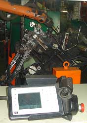
Two
ABB robot cells containing the Arcitec power sources were shipped to Criterion
for initial fixture and weld tests. The weld tests carried out at this time were
minimal as Criterion did not have the necessary weld process expertise to evaluate
the Arcitec or any power source. The two units were then shipped to VAW the tier
one supplier.
Since
the installation of the robot cells, continuous production of optimum weld quality
parts has been impossible due to the issues documented in this report. Weld
reject rates averaged sixty percent and the robot down time per hour averaged
20 to 30 minutes.
Many issues are documented and I have not included
them all in this report, however the primary cause of the extensive weld quality
and productivity issues at VAW was the ABB Arcitec power source . This
weld equipment had extensive electronic problems. The bottom line is the weld
results were inconsistent and unsuited to the needs for the high volume, small
welds on the thin aluminum parts.
Arcitec
Power source History.The
Arcitec power source was manufactured by ESAB in Sweden in the late 1990s. The
Arcitec was an inverter pulsed GMAW power source. This power source was integrated
into the ABB S4/S4C robot controls in an attempt to improve the communication
"response time" between the robot controller and welding power source.
I have extensive knowledge of Arcitec power source issues, as I was previously
employed by ABB, the Swedish manufacturer of robots. My position with ABB was
weld manager / senior weld process engineer. Part of my responsibility was to
evaluate the application performance of new welding equipment which included the
Arcitec.
I have evaluated many power sources during the last three decades and cannot
recall any welding power source that even came close to the amount of welding
Issues generated by the Arcitec. The bottom line, this equipment was introduced
by ESAB to the market place without sufficient testing by ESAB.
The
German marketing manager at ABB Fort Collins, made the mistake of believing the
Swedish sales spiel from the marketing manager at ESAB about the capability of
the Arcitec. Over 100 units were ordered to be installed in the ABB robots for
North America. As I tested the Arcitec and found the erratic performance and many
other issues, I documented the faults and the demonstrated the issues to the ABB
marketing manager, as this manager had foolishly ordered approx one million dollars
worth of Arcitec inventory he was not happy with my reality and he ignored the
Arcitec test results and my reports.
 As
a result of the never ending software / hardware issues and erratic performance
from the Arcitec, eventually ABB did reduce it's focus and promotion of the European
ESAB package and instead focused on promoting either the slightly less inconsistent
Miller Invision, and Lincoln Power Waves.
As
a result of the never ending software / hardware issues and erratic performance
from the Arcitec, eventually ABB did reduce it's focus and promotion of the European
ESAB package and instead focused on promoting either the slightly less inconsistent
Miller Invision, and Lincoln Power Waves.
Four years after the introduction of the erratic Arcitec, I was requested by VAW
to evaluate their poor performing robot installations. I knew the installation
had an Arcitech power source, however I was under the impression that the poor
performing Arcitecs were taken out of service and I would be examining new ESAB
units that had evolved electronically from the original equipment I had evaluated
four years previously. What I saw while welding at VAW was I believe the same
Arcitech power sources which were manufactured four years earlier. The units I
tested at VAW certainly had the same unique electronic glitches causing burn backs
and other issues which I was familiar with, and the power sources still produced
an inconsistent output weld voltage and weld performance.
VAW History of Arcitec:
[] A few months after VAW accepted
the robot cells, "three Arcitec power sources were replaced" by ABB.
The typical life of a traditional MIG power source is 10 years without requiring
repairs. With the more sophisticated, inverter pulsed equipment one would anticipate
that this equipment should at least last till the warranty runs out, which is
typically two to three years.
[]
Five months after the robots were installed, the two robots with replaced Arcitech
equipment were unable to produce consistent, acceptable weld production or quality.
Weld reject rates were in the 60-70%% range and the production cycle efficiency
rarely attained 40%.
[]A
Primary Weld Issue. "Wire Burn Backs"
From a weld production
perspective the most serious issue was the numerous welding wire burn backs
which were generated during the arc sta