|
|
Welcome to the world's largest web site on Flux Cored and MIG Weld Process Controls & Best Weld Practices. This site section focusses on flux cored welds on ship building plate and flux cored and MIG welds on pipe.This is the necessary Flux Cored - MIG weld information and data necessary to attain the highest possible manual weld quality, always of course at the lowest possible weld costs.This welding web site was established in 1998 by Ed Craig. Contact Ed now Em at. ecraig@weldreality.com. Ed 21 8 19
Flux Cored Arc Welding, (FCAW) applications.
Welcome to web site where you will find practical, cost effective weld process and application information that cuts through the "play around" with the weld controls industry, and also cuts through the sales influence and flux cored weld process misinformation that is often prevalent in many weld shops.This web site was started in the 1990s long before google and before the word blog. You will note on the site that the date is often added when the weld comments were made. You will also note with time that's measured in decades, that the common, global, daily weld issues rarely change.
It could be 1969 or 2019, so what is new in your weld shop?


The hardest thing to do for many weld shops
has been, to
"introduce change".
THE WELD INDUSTRY HAS ALWAYS PLACED MINIMUM FOCUS ON THE IMPORTANCE OF FLUX CORED AND MIG BEST WELD PRACTICE AND WELD PROCESS CONTROL EXPERTISE. IT SHOULD THEREFORE BE NO SURPRISE THAT OVER 3 DECADES, THE ALL POSITION, GAS SHIELDED FLUX CORED PROCESS HAS SUFFERED & SLOW PAINFUL ACCEPTANCE
AND RARELY ATTAINS ITS WELD CAPABILITY POTENTIAL :
The development of the highly cost effective small diameter, gas shielded flux cored wires by Alloy Rods was one of the most important weld process - consumable contributions to the global weld industry during the last plus three decades. However the slow growth with the acceptance of the FCA consumables is unfortunately a reflection of the lack of process expertise by too many managers, engineers and supervisors throughout the global weld industry.
As we head towards 2015, there are still numerous large weld shops especially those in the construction, oil, gas, chemical and power industries that still ignore, under utilize or use the FCA process without the process control - best practices required, and in these shops you will still find that the prime process for all position, code quality welds is the inferior, more costly Stick (SMAW) process.
When the weld industry is provided with a process or consumables that can provide extensive cost savings, and that process is easy to use, it means someone in the "we dont like change weld shops" will have to drive the process - consumable changes and therefore, managers, engineers, supervisors and technicians have to step up to the plate and take the process ownership and provide the process control - best practice training that is necessary, (training thats rarely provided). This training would enables weld personnel to consistently produce optimum, all position, flux cored weld quality and productivity, without weld personnel "playing around" with their weld controls.
To optimize either the MIG or Flux Cored weld process control expertise in any weld shop is a simple task if the weld shops utilizes my self teaching - training resources.
A QA STAINLESS FLUX CORED ISSUE:
E-mail Question: Sept. 2007:
Hi Ed. My AWS approved weld inspector was working with a new application using 316 stainless flux cored wires. We had not used this weld wire before, so he set up a weld qualification test. The weld inspector ran the procedure with the 316 flux cored wire and said we should use a helium tri-mix containing 90% He / 7.5% Ar / 2.5% CO2 . The welds look cold, and when we sectioned the welds, we found lack of fusion, porosity and slag inclusions. The inspector told me that he got the gas information from AWS and they said the tri-mix could be used for this. I think he's made a mistake. I have never heard or seen where the tri-mix can be used for flux cored. Ed, do you know if the welds can pass mechanical test requirements with this helium tri-mix.
Ed's Answer: It's hard to believe that 30 years after the introduction of the common steel and stainless flux cored weld wires, that so much misinformation is daily utilized in weld shops. These wires would have been qualified with either with argon - 25% CO2 or straight CO2. Its sad that someone who has a responsible role in a weld shop, would try to qualify stainless flux cored welds with a helium tri-mix. With the highly inert tri-gas mix, (missing a large amount of CO2 with it;s dissociation properties) you will have extensive lack of weld fusion, extensive porosity and slag entrapment. The high inert content will also create welds that exceed their maximum strength with typically end with weld ductility. Its been my experience that If you want sound weld advice, the last organization you would ask is the highly profitable, "none profit" AWS organization. Use the argon - CO2 or straight CO2 as recommended by the wire mfg and tell that inspector that a great flux cored process control training program is available here.Words that really annoy me in a weld shop.
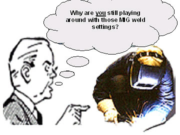
When weld personnel play around with MIG - Flux Cored weld controls,
this means the management has not provided what?
In the world where too many global, hands off managers, supervisors and engineers, don't question why there are so many daily, costly weld issues being generated on the weld shop floor, or why the so called experienced manual welders or robot technicians “play around”with the two control MIG or flux cored weld process, you would not expect to find anyone in the front office that fully understands the processes utilized or the real costs of the welds they daily produce.
The good news for weld management is with the right qualified weld leadership, and the bigger the weld project, the greater the the weld cost savings potential:
In 1969 or 2019, thanks to the common lack of management weld process control expertise you typically will find tremendous weld cost reduction potential has always been found in ship yards, large construction projects, refineries, oil platform construction and of course at the other end of the spectrum, the infamous poorly managed global auto - truck plants:
.
STICK - TIG - MIG - FCA OR THE TIP TIG PROCESS?
YOU WOULD THINK THAT IN THE INDUSTRIES AS SHOWN ABOVE, OR WITH ANY COMPANY THAT PRODUCES EXTENSIVE MANUAL OR ROBOT MIG - FLUX CORED WELDS, THAT THE WELD MANAGEMENT, ENGINEERS AND SUPERVISORS WOULD HAVE A FULL UNDERSTANDING OF HOW TO FULLY CONTROL WELD COSTS, AND TO ENSURE THAT "ALL THE EMPLOYEES" INVOLVED WITH THE WELD PROCESSES WOULD AT LEAST HAVE THE REQUIRED WELD PROCESS CONTROLS - BEST WELD PRACTICE EXPERTISE THATS NECESSARY FOR CONSISTENT WELD PROCESS OPTIMIZATION.
Please remember: Welders skills or the length of the welders experience, has nothing to do with the weld process control expertise that enables weld personnel to attain optimum, consistent weld quality, always at the lowest weld costs
Weld Fact: Few industries will use more flux cored or MIG wires in their day to day applications than a ship yard or auto - truck plant, and no one will typically will have greater weld repairs and weld rework costs per-foot of weld than these two industries, two industries which ironically will have a greater ENGINEER to WELDER RATIO than most other industries.
2000: IN MANY GLOBAL SHIP YARDS, WELD RE-WORK COST PER-SHIP IS OFTEN MEASURED BETWEEN ONE AND TEN MILLION DOLLARS. WITH THIS IN MIND, IT'S DIFFICULT TO UNDERSTAND WHY THE MAJORITY OF GLOBAL SHIP YARDS HAVE NOT ESTABLISHED BEST MIG & FLUX CORED WELD PRACTICES, AND WHY THE MANAGEMENT HAVE NOT PROVIDED BOTH THEMSELVES AND THEIR EMPLOYEES WITH MIG AND FLUX CORED WELD PROCESS CONTROL - BEST PRACTICE TRAINING:
Many mangers are under the impression that theyhave an effective welder training department or that the local commuinity college can provide what they need. However, the mangers are often not aware that the welder skills taught are often not relevant and the education provided rarely has nothing to do with controlling the weld process or with being aware of the best weld practices. How do i prove this point?
PICK A FEW OF QUALIFIED WELD PERSONNEL. PROVIDE THEM WITH EITHER THE FOLLOWING MIG OR FLUX CORED TEST. THEN ASK YOUR SELF, ARE THESE QUESTIONS RELEVANT TO THE SUCESS OF MY COMPANY.Try Ed's Flux Cored Process Control Test.
Try Ed's MIG Process Control Test.
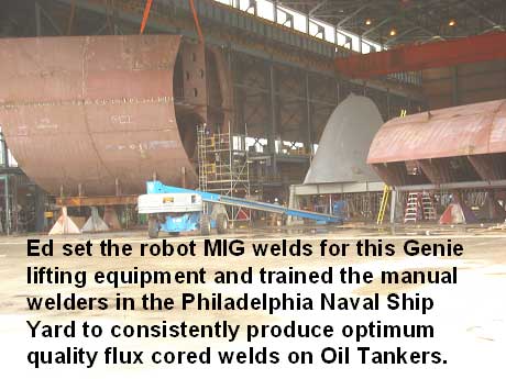
WHEN I USED MY UNIQUE, MIG / FCAW WELD CLOCK CONTROL METHOD THAT SIMPLIFIES WELD SETTINGS WITH MY WELD PROCESS CONTROLS - BEST WELD PRACTICE TRAINING METHODS, (DEVELOPED OVER THREE DECADES), TAKE A LOOK BELOW AT THE FOLLOWING MULTI-MILLION DOLLAR, ANNUAL WELD COST SAVINGS THAT I ACHIEVED IN A FEW MONTHS AT THE AKER KVAERNER SHIP BUILDING FACILITY IN THE PHILADELPHIA NAVAL SHIP YARD.
Its not difficult for any Ship Yard to save millions of dollars per-ship by reducing
the daily FCA - MIG weld rework, and increasing the weld productivity.
In 2007, With their flux cored weld repair costs per-ship somewhere between 7 and 9 million dollars. I was hired by Aker as the ship yard weld manager. My first task was to try to get control from the German mangagers who were responsible for the weld cost issues, and my next task was to to provide the approx. 300 welders with my manual flux cored weld process control training program.
The welders in the ship yard were using the E71T-1 0.045, (1.2 mm) gas shielded flux cored wires. These wire were used to weld all position, typically 12 to 25mm, carbon - low alloy steel plates with Vee Grooves and ceramic backing for the root welds.
As with many ship yards in 2007, the mostly German - European yard management at this USA yard was stuck in a 1950's Weld Time Warp. While the managers, QA personnel and supervisors had a good understanding of the SMAW (stick) process, they had almost no weld process control - best practice understanding of either the MIG or flux cored process, two processes that were responsible for most of the ship welds, and two processes that responsible for the millions of dollars in costly weld repairs per-ship.
At this Aker yard, the weld training department focus had been on skills entrenched with SMAW (stick) weld practices. There was no training focus or understanding on the Weld Process Control or Best Practice expertise that has always been necessary to attain consistent optimum results from flux cored welds that are daily influenced by numerous variables in the yard.
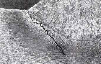
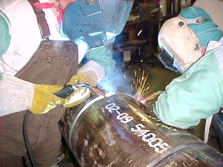
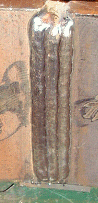
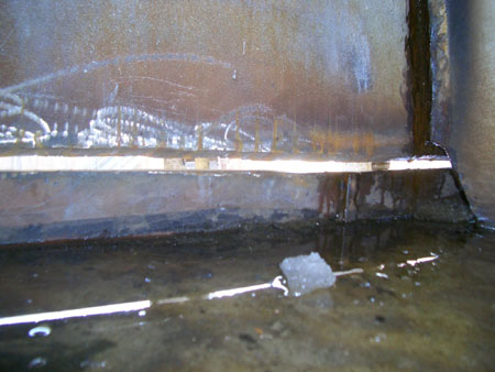
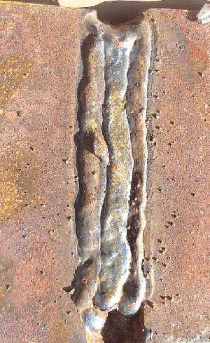
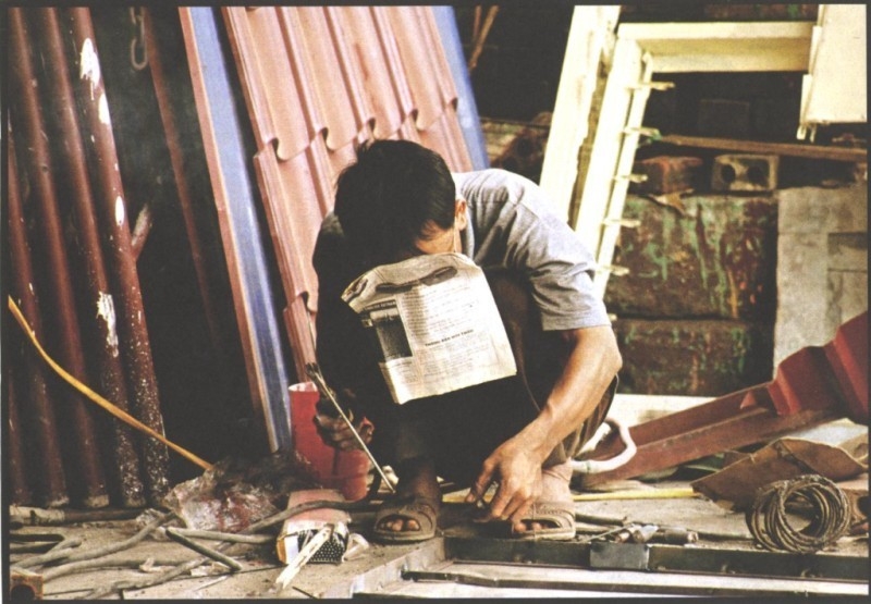
Of course also like most global ship yards, the welders had to pass the TIME & DOLLAR wasting, all position, "Multi- Pass", flux cored, VEE groove plate weld qualification tests. You can see the result of one test from the photo on the right. This welder qualification test coupon was from one welder in the yard who had previously qualified with the ABS test and the flux cored process. This welder had also been welding on the ships for a few years.
TSome of the best ship weld quality that I have ever viewed was on S-Korean ships.
WHY THE AMERICAN BUREAU OF SHIPPING (ABS) WELDER QUALIFICATION TESTS AND MANY OTHER THICK PLATE GROOVE WELD QUALIFICATION TESTS, HAVE FOR DECADES BEEN INNEFFECTIVE, AND A WASTE OF TIME AND MONEY.
There are many things that will influence the welds that are made in the ship yards.
;
[] poor or inappropriate welder training programs.
[] lack of weld process - consumable and best weld practice knowledge,
[] weld procedures that are not optimum as they rarely deal with the real world variables that daily influence the welds.
[] poor choice of weld equipment and consumables,
[] inexperienced managers, engineers and supervisors,
[] the lack of fabrication department ability to provide weld joints that conform with weld joint design requirements.
[] Lets also not forget, the usual QA and inspection practices that too often waste their resources trying to find (sometimes) weld defects, rather than being part of a cost effective inspection team that's been trained with process expertise to prevent weld defects.It does not take long in most ship yards to see poor fabrication - poor weld practices and poor choices of weld equipment or consumables. It's also difficult to find weld personnel that know a little aout the weld process and weld consumables they daily utilize.
Its a wonder sometimes how so many ships stay afloat after leaving the dry dock.
From a design / strength perspective, the center area of a ship is typically the weakest link, its also where the highest weld quality is supposded to be. The middle longitudinal amd horizontal flux cored welds seam on a ship typically will get 100% X rays, and then for a reason likely influenced by costs, there will usually will be a lower "Visual" or small percentage NDT inspections typically applied for the rest of the welds.
In ship building;
[1] Its a rare event to find welds without the type of defects that can influence failure.
[2] Its a rare event to find that all the weld edge preps have their specified dimensions, angles and required cleanliness.
[3] Its a rare event to find that all the welds were carried out with the correct preheat and interpass temp controls and that the weld joints were protected correctly from the environment.
Note: As you can see with above ships weld preps, the fitters in this ship yard must have got their training at Walmart and the engineers, QA personnel, supervisors might as well have stayed home.
One thing ignored in many ship yards is a "small fraction of an increase in the groove root opening" beyond that specifed will dramatically increase the number of weld passes required. The additional weld heat from the extra weld passes can influence, enlarge and weaken the steels Heat Affected Zones, esecially when the good practice of interpass tem controls are not applied which again is the norm.
Note: With larger than normal HAZs, mechanical strengths are decreased and minor weld defects will have more of an opportununty to influence weaker HAZ.
Each year, ships that typically can cost 100 to 500 million dollars, will in decent weather, simply tear apart and sink, yet no one seems to know why. However with the ships in which someone as above, managed to take a photo before the deep plunge, the destructive metal tears will Imn sure in most instances follow the welds, and if you are looking for root causes of poor weld quality and over heated weld HAZ locations, simply track down the engineering and QA management at the yards where the ships were built.
THE TYPICAL FCA SHIP WELDS PRODUCED AROUND THE GLOBE WILL SUBSTANTIATE THIS POINT OF VIEW. For those of you that disagree with my comments on the typical code MIG or flux cored, groove, welder qualification requirements, or on the value of my weld process control training programs, please remember that at this Aker yard in a matter of hours, I took > 250 welders, many who in reality should never have been allowed in the yard as a welder. And after my two day process control training program, we sent them back out to the yard. Over the next few months the skeptical QA department management religiously tracked and reported the weld rework labor - NDT - consumables reduction costs for one ship. They then followed up with a report to the yard management that the savings at that time were close to 6 million dollars.WELD QUALIFICATION TESTS SHOULD START WITH WELD PROCESS CONTROL & BEST WELD PRACTICE TRAINING. The reason that the ABS and also some of the AWS welder qualification tests on thick plate that require multi-passes are usually a complete waste of time and money, is once a welder has shown the ability to provide an optimum, "vertical up single pass. 1/4 fillet weld", that welder has proven their skills necessary for any weld. Therefore all that should then be required is that the welder be taught the process controls for the process - consumables utilized, and the best weld practices necessary to comply with real world weld procedures, and with the typical numerous ship yard variable that influence the welds.
Note: Another issue for many weld shops. is the shops may use incorrect flux cored weld wires or the wrong wire sizes, or perhaps they use flux cored or metal cored wires when the welds could be achieved with the MIG process with it's much lower cost weld wires.
AN EASY LOW COST WELD THAT PROVES THE WELDERS SKILLS FOR ANY "ALL POSITION" PLATE WELDER QUALIFICATION.
Using an 0.045 (1.2mm) E71T-1 wire. Produce a single pass, 1/4 (6.4 mm), vertical up, steel fillet weld, thats six inches in length. Use 3/8 plate thats free of surface contaminates and mill scale. This low cost weld should be the only welder qualification test ever required for any positions VEE or J groove plates. To test the weld fusion attained, provide a break test in a vice. This will reveal the internal quality of the weld.
Note: For a plant that implements it's own welder qualification, If welding > 3 mm, carbon - low alloy steels in the flat - horizontal weld positions. And the welds are on metals free of surface contaminates, simply have the welders on 6 - 9 mm plate, provide a single pass, 1/4 (6mm) horizontal fillet, (one side). Use the Spray mode. Beak test in large vice.
WE NEED A 100 WELDERS FOR THE YARD. WE HAVE TESTED 400 AND YET ONLY 50 PASSED THE TEST.By the way many ship yards when trying to hire drug free welders, require for a welder test that the welders use their own wire feed and voltage settings. Remember in this play around with the weld controls industry, the flux cored and MIG are processes that most weld personnel (including experienced) have not received process control or best practice training. Also many of the welders taking a test will have to weld on none conductive ceramic root backing material which requires specific settings and unique weld practices which are rarely used outside a ship yard or storage tank mfg. And the yard management wonders why so few can pass the welder qualification tests. Note: The ceramic flux cored weld practices and opt settings are covered in my flux cored training program.
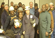
Ship yard weld personnel, great characters, many with weld experience, the majority lacking flux cored and MIG weld process control expertise. Some of my goos freinds that I was training at Aker in the Phily Naval Yard.
WHY THERE SHOULD NEVER BE A CONCERN FOR THE SHORTAGE OF WELDERS.
As i have mentioned many times on this site, and as I have done at numerous weld facilities, when the weld shop employs weld management - engineers and supervision that has expertise in weld process control and best weld practices, that shop should be able to take someone who has never welded and with 5 to 8 days with my recommended training program have them pass any weld code requirement, all position welds using either the MIG or flux cored process.
Question. Ed what is a weld professional?
Answer: A professional welder is someone who fully understands the metals welded, the common arc weld processe and consumables utilized, the weld process control requirments, the best weld practices, and provide the necessary skills required for each application.
In North America, hundreds of thousands of man hours and millions of dollars are wasted annually on producing ineffective plate flux cored or MIG welder qualification tests.
The above welders are taking the standard ABS gas shielded flux cored welder qualification test for a ship yard. From my perpective they are wasting their companies time and money putting "multi- pass" flux cored welds that simply repeat the welder's capabilty many times. An irony also is most of the welder are also using a weld process and consumables for the test, and yet its likely that both they and their supervisors, do not fully comprehend the weld process and consuamble requirementsto necessary to attain weld process optimization out in the ship yard. O well its only been this way for sixty years.
SO YOU REQUIRE A LARGE AMOUNT OF FLUX CORED OR MIG WELDERS FOR A PROJECT.
[1] Be aware that it does not matter if the individual has or has no weld experience. First put the potential new employees in a classroom. Provide them with my process control & best practice training for either the flux cored or MIG process. My classroom training requires approx. 6 hours
[2} With my process controls - best weld practice information learnt, you would allow the welders or rookies using the settings and best paractices learnt, 1 to 2 day for hands on training. My recommendations for the hands on training are spelt out in my training programs. During the hands on, the welders would be examined for their attitude and ability to control the weld gun. Note at this time the weld trainer decides if the weld person is ready for the welder qualification tests, should be let go, or requires a few more hours of hands on training.
.
[3] When ready to do their Welder Qualification Tests, the welders will now know how to set optimum, fine tuned weld parameters, and be aware of the required best weld practices and techniques that will ensure optimum weld fusion with the lowest possible trapped slag or porosity.When you train any personnel so that they understand the process they use, and give them the optimum best weld practices and techniques that are required for the consumables and applications they work on, you should be able to get at least 8 out of 10 personnel through any welder qualification test and thats weld cost effective. Please remember I have done this on numerous occasions, it works
AGAIN, WHY IS THAT COMMON THE MULTI-PASS WELD QUALIFICATION TEST IS A WASTE OF TIME AND MONEY.If a welder using the common E71T-1, gas shielded flux cored process can provide a one side, vertical up 5 - 7 mm fillet weld that will pass a break (vice) test, that welder should be capable repeating that weld and therefore when provided with FCA weld process controls and best weld practice training pass any position groove plate weld test.
2000: From Ed's flux cored training program. All multipass all position groove welds should be made up of 5 - 6 mm fillet size stringer beads. The weld data is set for either a flat which is also used for horizontal welds, or for a Vert Up fillet beads which is also used for over head (and all cap welds. The stringers with the optimum size weld energy to mass ratio, are directed at the location requiring the weld fusion.
KEEP PROCEDURES SIMPLE AND EFFECTIVE. AND ENSURE THE PROCESS TRAINING PROVIDES THE FOLLOWING TWO SETS OF DATAMost weld defects will occur from the root to the next two passes. Lack of fusion porosity and slag issues will be dramatically reduced if manual welders are not allowed to use weld weaves.
On any welder qualification test or in any plate goove steel flux cored application;
A ceramic root and cap weld stringer passes will use the same flux cored "low" WF - volt settings.
All vertical up and over head goove welds will use one WF - volt setting.
Flat and horizontal positions will again use one higher WF - volt setting. These flux cored for all plate and pipe tests, and you know where to find those optimum plate or pipe weld settings.
As we are all hopefully aware, when optimum, multi-pass welds are required, that weld will be best served with 5 - 7 mm stringer beads (as shown above). These stringer welds which are easy to control, will have about the same weld mass as found in the common 6 mm fillet welds. A 6 mm fillet should have excellant proportion between the weld energy provided and the weld mass produced.
If a welder can pass a simple, single pass, fillet weld break test for the weld position desired, it makes no sense for that welder to keep repeating the stringer welds over and over again. I dont believe that most weld codes stipulate that it's a bad weld practice to allow manual welders to use weaves on code quality applications, if however welders avoid weaves they will get many weld benefits..
IT TAKES A FEW HOURS TO PROVIDE WELDERS, SUPERVISORS, INSPECTORS, AND TECHNICIANS WELD PROCESS CONTROL & BEST PRACTICE TRAINING, AND ALSO TRAINING THAT DEALS WITH THE VARIABLES THAT WILL INFLUENCE THE WELDS ON THE JOB.
CERAMIC BACKING FOR FLUX CORED WELDS REQUIRES SPECIAL WELD CONSIDERATIONS AND UNIQUE WELD PRACTICES THAT ARE RARELY GIVEN:
Not only is the a general lack of both MIG and flux cored weld process control expertise a problem in ship yards, its also common in these facilities to find that many of the weld personnel lack an awareness of the unique flux cored weld process control - best practice requirements which are necessary to control the all position groove welds made on the unique NONE-CONDUCTIVE Ceramic root backing materials.
My FCA training program focussed on the flux cored Weld and Consumable Process - Parameter and Control requirements, with the required Best Weld Practices necessary for all position, groove welds with open root ceramic backing.
In a time of welder shortage, when many companies find it difficult to interrupt their daily productivity, management take note, my easy to present, process control training program requires eight to ten hours classroom time to present. You than provide four hours with hands on time to enable the weld personnel to use what was taught in the classroom. In a few weeks, the weld training for the 300 plus welders, engineers and supervisors was complete, and the ship yard QA department started to analyze the results..
YAWN 60% WELD COST SAVINGS BUT WHO IS TAKING NOTE: A few months after the process control training I provided, the Aker ship yard's quality control management indicated at least a 60 % reduction in the required weld rework per-ship. The ship yard reported that the reduced weld rework, labor and NDT costs, would result in a minimum cost savings of approx. $6 million per-ship.
MANY WELD COST BENEFITS ARE DERIVED FROM A FEW HOURS OF CUSTOM PROCESS CONTROL TRAINING:
Examine the real world ship yard weld cost reductions and benefits for Ed's unique training program that is so simple you dont need weld expertise to present it. The Aker training program required approx. 300 weld personnel x 8 man/hr. = 2400 man hours at an approx. $30/hr, = base labor cost for the ship yard of $72,000. for this training program. To this add the actual training costs of approx. $100,000.00 = for a total training costs of approx. $172,000.
INITIAL WELD COST SAVINGS: With weld rework costs lowered by 4.5 million dollars per-ship and training costs approx. $172,000, its not hard to figure out if the training was cost effective. Also an unreported fact from this yard was the changes that I established in the new weld procedure wire feed settings. The increased flux cored wire feed rates, (weld deposition rates) increased the daily weld productivity per-man in a range from 20 to 40%.
THIS IS NOT THE STANDARD TRAINING SHIP YARDS ARE USED TO: Some of you may wonder what's the difference between this type of weld training program and the MIG and flux cored weld training you could expect in any North American, Korean, Chinese, Japanese or European ship yard?
For decades conventional welder training in ship yards or manufacturing plants has focussed on the welders skills, especially on stick (SMAW) welding skills which is ironic as this low deposition high rework proce has nothing in common with eith the MIG or flux cored process. With the conventional flux cored training, it's not unusual for weld personnel to have many weeks of hands on training at the ship yards and at the training completion find out they will;[a] play round with the MIG equipment weld controls,
[b] utilize the FCA weld controls in a very limited manner,
[c] rarely utilize the best FCA weld practices - techniques for the specific applications.
It took six hours in the clasroom with my process control training to go from this to this.
.
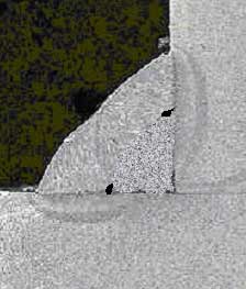
As you can see with above the LEFT picture, we have a sad looking Vertical Up, Vee Groove plate weld. The weld wire used was E71T-1. This welder qualification test was made by one of the ship yard qualified welders who from my perspectiveshould never have been allowed near a MIG power source. This individual, (I will not call him a welder) was out there in the yard making welds like this all over the ships, and the weld inspectors rarely took a second look.
The other picture, above RIGHT is an untouched, vertical up, flux cored weld. This weld qualification test piece was made by the same welder who made the weld on the LEFT two days earlier. The welder used the same consumables, and after only 6 hours of my classroom process control training and 4 hours hands with the the best weld practices, the changes were dramatic. While the vertical up welds on the right were not optimum, the multi-pass welds did pass both an X-Ray evaluation and bend tests, and for the Aker ship yard share holders, that's money in the bank.
Even when the welders have the highest possible skills, this type of training allows them to optimize the performance of the tools (weld equipment) they uses which increases both the weld quality and productivity capability. What was also important, was each welder became aware of the unique flux cored weld parameters and technique and best practice requirements necessary to address the extensive different size root gaps over the ceramic. With all weld personnel the process training will ensure weld productivity will typically be increased in the 20 to 40% range and their will be an instant reduction in lack of weld fusion, slag entrapment and porosity defects.
The improvements by all the welders was immediately noticed by the ship yard QA management who's inspection employees measured the dramatic weld cost improvements evident through the required NDT and weld rework man hours. Aker initially gained at least 5 - 6 million dollars per-ship from a weld training program that with a loss of man hours from the yard was a cost of approx. $170.000. By the way, few global ship yards or manufacturing facilities examine the cost effectiveness of the costly training programs they develop.
Special thanks to Tom O'Malley (blue jkt above). Tom was like a brother to me, he is now deceased and really missed. Tom assisted me with the training program. By the way Tom was one of those rare owners of a weld supply company that actually spent many hours per-week evaluating the weld processes, equipment and consumables he sold.
Major MIG - Flux Cored weld quality - productivity problems with Canucks and Canadian Frigates:
Neither the Canadian Navy or the North East Canadian ship yard management were aware that there was daily weld process chaos in the ship yard:
TO FIGURE OUT HOW POOR THE WELD QUALITY & PRODUCTIVITY WAS AT THIS CANADIAN YARD WAS, LETS START OUT WITH AN EXAMPLE OF WHAT WELDERS WHO ARE CORRECTLY MANAGED SHOULD BE ACHIEVING WITH COMMON MIG AND FLUX CORED WIRES USED ON SIMILAR STEEL APPLICATIONS.
During the nineteen nineties, I was invited to provide a weld evaluation for a large, North East, Canadian Ship Yard. The yard had a contract to build Frigates for the Canadian Navy. After a tour of the yard, I found that the welding practices used by most of the welders could only be defined as "beyond chaos".
The engineering - production management at this Canadian ship yard had enabled extremely poor, numerous and inappropriate weld practices to be used to construct the Frigates. There was a complete lack of understanding not only by the yard management but throughout the yard from the majority of weld personnel with both the MIG and flux cored weld processes which were the two prime processes utilized. It was also interesting to note, that thanks to the lack of management process ownership and weld accountability from the yard management - supervison, the few weld engineers in the yard that had an inkling something was wrong, were not allowed to correct the welders and tell them what to do. The bottom line was the ship yard weld quality and productivity was run by the yard welders, and the vast majority of these welders lacked an understanding of the MIG and flux cored processes utilized.
In a well managed weld shop, when welding common, 1/4 (6mm), horizontal fillet welds, using either an 0.045 MIG or flux cored wire, the welders would produce a single pass weld with the following.
[] With the 0.045 MIG wire set for a Spray weld, or with the 0.045 flux cored wire, typical wire feed settings of around 420 - 450 inch / min, with around 28 - 30 volts. Both of these two weld processes would attain a typical, average weld deposition range of approx. 9 - 11 lb/hr. Many welders would average about twenty minutes (30%) an hour of actual arc on time. Each 8 hr shift the welder would deposit approx. 24 pounds of weld.
Note: A reflection of the common poor ship yard weld management is they will often find their welders in an 8 hr shift may average 10 - 15 pounds of weld metal. If you simply ask the purchasing mgr how many pounds of the two most important weld consumables are purchaed each year, then divide by the weld man hours for the year the ship yard weld efficiency can be readily worked out.
WELD COSTS CAN BE REALY SIMPLE WITH MIG and FLUX CORED WELD PROCESS CONTROL EXPERTISE.
I DEVELOPED AN EASY WAY TO EXAMINE THE WELD PRODUCTIVITY
PERFORMANCE FACTOR FOR ANY LARGE WELD SHOP.
To compete in a global weld market in which the Chinease are building - welding bridges for the state of California, and maybe one day frigates for the US navy, one would think that engineering management involved with any large scale weld projects would at least understand the daily weld production deposition potential. and the daily weld deposition rate potential per welder.
In a large weld shop where most of the welds are an parts > 3 mm, and welders soley weld while someone else does the fitting, if you multiply the total welder man hours for the year by 3, you will see how many pounds of MIG or flux cored weld wire should at minimum be deposited daily. .
WHAT'S ACCEPTABLE WELD PRODUCTIVITY WITH ALL STEEL MIG - FLUX CORED APPLICATIONS?
The average MIG and Flux Cored weld wire usage per eight shift day for weld shops welding;
[] Thin gage parts < 3 mm, welders should be depositing between 8 - 10 pounds per shift.
[] Parts that are typically in the range of > 3 mm to 12 mm, the daily deposition should be 22 - 25 pounds.
[] Parts that are typically over > 10 mm, the daily deposition should be 25 - 32 pounds.
Note: The majority of the 1000 plus companies that were large users of MIG - flux cored weld wires were typically achieving 40 - 60% of the welds that would have been deposited in a weld shop in which employees were provided with my process control training programs.
Management that lack process expertise will often encouraged the welders to go BIG.
These 15 mm, single pass fillet welds made in flat position on rock crushing equip - high strength steels) led to excess weld heat in the HAZ, that lead to very costly equipment failure. The management was not aware that smaller, stringer welds provide the same weld production with the faster weld speeds that also keep the weld heat input low.
WELD SIZE AND GOOD WELD PRACTICE: For those shops that think big single pass weld are the way to go. With optimum weld data and best weld practice, single pass welds are fine with horizontal fillet welds up to 5/16. When the "horizontal fillet" weld size required is larger than 5/16, the weld management should have concern for lack of side wall weld fusion and for the heat effects in the HAZ from the slow weld speed. The solution for the welders to use 1/4 stringer beads. I rarely would allow manual, horzontal weld weaves to be used for fillet welds above 5/16 as lack of fusion will occur from the weave inconsistencies. Also excess weld heat will be generated from the large welds and slow travel rates.
Carbon steels, limit manual, horizontal single pass fillet welds to 1/4. For flat position welds limit single pass welds at 1/2.
High strength steels or steels that are heat sensitive, restrict all single pass, horizontal and flat position welds to 1/4 stringers .
THE MAJORITY OF THE WELDERS IN THE CANADIAN YARD WERE USING THEIR TWO PRIME WELD PROCESSES WITH WELD PARAMETERS AND PRACTICES THAT WERE GUARANTEED TO PRODUCE EXTENSIVE LACK OF WELD FUSION.
At this ship yard, to make the common 1/4, carbon steel, horizontal fillet welds on the frigates, the ship yard welders would use two welds that were carried out with two weld processes, MIG and gas shielded flux cored.
SOMEONE DID NOT TELL THE WELDERS IF YOU USE LOW AMP WELD PARAMETERS, YOU END UP WITH SOMETHING CALLED LACK OF WELD FUSION.
The Canadian ship yard welders when making a horizontal fillet weld, would do the following.
[] When welding 6 - 12 mm steels, the welders would use two weld passes and have their MIG equipment set with MIG low energy, spatter producing, Short Circuit or Globular wire feed settings that would typically deposit on average 6 lb/hr or with a twenty minute arc on time 2 lb/hr. No one could answer why the welders were using short circuit with the MIG wires, the reality was it was hard to find someone in the yard that knew what short circuit was. The MIG short circuit parameters utilized throughout the yard would have been better suited to welding hin gage 0.080 sheet metals. This first short circuit fillet pass had to result in extensive lack of weld fusion.
[] For the second pass the welders changed their weld process to flux cored. With flux cored they actually made no weld parameter changes. The flux cored settings ensured the welders would put cold flux cored welds over the top of the cold short circuit welds.
[] The two fillet weld passes were welds that had more lack of fusion than fusion, and the cold flux cored welds had extensive slag entrapment. Each day approx. 200 hundreds would use these poor weld practices while they put down thousands of feet of fillet welds on each frigate.
[] It may come as no surprise as I walked around the yard to discover that few in the yard knew what MIG short circuit, globular or spray was and even fewer understood the working range of the E71T-1 flux cored wires used
THE WRONG MIG WELD TRANSFER MODE WAS ALLOWED BY THE YARDS WELD ENGINEERS AND MANAGERS: The short circuit and globular parameters were used with the 0.045 (1.2mm) wire, set at a typical wire feed rate of 210 to 280 ipm, 5 - 7 lb/hr with 180 to 240 amps - 19 to 22 volts. Apart from the extensive spatter, without question, the majority of these welds would result in extensive lack of weld fusion, and reduce the deposition by 30% on carbon steel parts > 4 mm.
To add to the horizontal fillet weld problems generated at the yard, the MIG welds were then followed by a second cold weld pass made with an 0.045 (1.2 mm), gas shielded "all position" E71T-1 flux cored wire. The flux cored wire used the same voltages and wire feed settings used with the short circuit MIG settings, 210 to 280 inch/min. (5 - 7 lb/hr). At these wire feed and volts settings, the fast freeze, E71T-1 flux cored wires used at these low settings had to ensure a massive amount of lack of weld fusion with the horizontal fillet welds.
Note: The flux cored wire feed settings used for the "horizontal" fillet welds, were very low settings. To make a single pass, horizontal,1/4 fillet with the 0.045 flux cored wires, you would typically use a wire feed rate of approx. 500 inch/min, (11 lb/hr) with 27 - 28 volts.
The Canadian frigate fillet welds under discussion only required visual surface examination, however the majority of the welds in this ship yard would in my book never meet the definition of a sound weld.
The prime purpose of the weld is hopefully to fuse two parts together,
.
To put salt in the Canadian Frigates ship yard management wounds, every weld produced with the low wire feed (low deposition rate) settings, took each of the 300 welders approx. 50% longer than it should have. This Canadian yard spent over a million dollars annually on welder training which was producing extraordinary poor weld quality and over seven million dollars per year on unnecessary weld labor costs.
I delivered my weld report to the yard management. The report provided the required data and practices for the yard to get it's welds to the quality and productivity they should have been attaining.
I was later informed that my weld report never got as far as the first manager who reviewed it. The report then disappeared. I was later told by a weld suppler to the yard that the manager was too embarrassed to present the report to his executive team and also he did not want the Canadian Navy Brass to be aware of the weld quality produced and the unnecessary yard over costs generated by the welds.
ALL WELD DECISION MAKERS SHOULD FOCUS ON THEIR EMPLOYEES UNDERSTANDING OF BEST WELD PRACTICES & WELD PROCESS CONROLS. WITH THESE SELF TEACHING OR TRAINING RESOURCES, IT'S EASY WITH THIS EXPERTISE FOR QUALIFIED WELD DECISION MAKERS TO GENERATE MULTI-MILLION DOLLAR COST SAVINGS ON ANY LARGE SCALE WELD PROJECT
THE SHIPS STRUCTURAL WELD FAILURES USUALLY FOLLOW THE WELDED JOINT SEAM AND THE SOLUTIONS TO AVOID THIS ARE SIMPLE
400 to 500 ships each year go down like this. As the ships split apart from in what appears to be the weld seam locattions,
does anyone give a dam that the ship yard likely did not deliver the ship in accordance with it's design - build sprecifications?.
If you are teaching your self, or providing weld process control training for others, my weld control resources are the key to attaining MIG and flux cored weld process optimization.
Item.1. The Book:"A Management & Engineers Guide To MIG Weld Quality, Productivity & Costs"
Item 2. A unique Robot MIG training - self teaching resource.
Item 3. A unique manual MIG training - self teaching resource.
Item. 4. A unique Flux cored training or self teaching resource.
Item 5a."Proceso de Soldadura MIG Manual"
(MIG Made Simple. Self teaching in Spanish).
Item 6a.The Self Teaching MIG Book/ Video.
Visit Ed's MIG / Flux Cored weld Best Practices - Process control training resources.
For those young guys getting into the weld business, remember weld process - application diversity, makes for a great weld engineer, technician, supervisor, and one day a weld manager.


WELD COSTS....This
is the world in which North American and European weld shops have to now compete.
There is always a place for SMAW welding, but from a weld quality and productivity and cost perspective, management woul ensure it's use is limited.
|
IF YOU DO NOT HAVE A SENSE OF HUMOR, YOU SHOULD NOT BE AT THIS SITE OR IN THE WELD INDUSTRY
In England we use to call a joke a "crack" I guess it applies above.
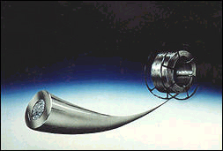
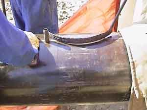
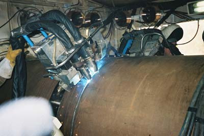
IN 1997 I CREATED THE FIRST NORTH AMERICAN PIPE WELDING ROBOT:
AS THE ABB WELD MANAGER I WAS WELL AWARE THAT A SIX AXIS ROBOT HAS ALWAYS BEEN ONE OF THE MOST VERSATILE TOOLS THAT COULD BE USED FOR ALL POSITION PIPE WELDS.
.
During 1997, when robots were wonky and weld soft ware was unreliable, I set this ABB robot To weld a 48 inch pipe. I used short circuit transfer for the vertical down root. I made the robot pipe fill pass welds in the vertical up position using an 0.052 (1.4mm) Alloy Rod Dual Shield E71T-1 wire with 80% Argon - 20% C02 for both the MIG and FCA welds. The vertical up flux cord weld, produced a weld deposition rate of approx. "11 pounds an hour"
At that time, The high flux cored weld deposition rate, combined with the fast robot movement between welds, (faster than any other available automated pipe weld equipment) provides greater single gun pipe line weld production potential than any other available automated pipe weld unit using a single gun.A robot can provide many unique features for pipe welds.
[a] accurate, flexible through the arc weld joint tracking,
[b] adaptive controls that can compensate for different welding conditions,
[c] super fast speeds between welds,
[d] superior communication with the welding power source. Combined these features offer the world's greatest automated pipe welder.
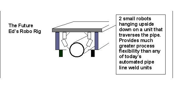
1997: Just imagine, one day we may then see two small robots hanging down, mounted on a "ROBO RIG" truck, that traverses that Texas, Canadian or Middle East pipe line producing weld deposition rates of 22 lb/hr.
1997: By the way at this time, the pulsed MIG process was little more an electronic joke.
How do you like my 1997 Robo Rig
In 1997: Ed created (IN HIS MIND) his "ROBO PIPE RIG"
[] My 1997 Robo Rig would have two robots hanging upside down using either the pulsed MIG or FCAW process. With the Robo Rig you would have a highly flexible robot unit that offers automatic touch joint sensing, through the arc impedance joint tracking, and adaptive weld controls that would readily compensate for any pipe joint deviations.
For that pipe line, drive the Robo Rig to the weld joint. In less than 10 seconds, the robots or robot will locate the pipe bevel and pipe root, in contrast setting track for two less flexible, two axis mechanized carriages can easily take 20 to 30 minutes.
[] With the pulsed MIG or flux cored weld deposition rates from the two robots at approx 20lb/hr, the Robot Rig will dramatically reduce the total pipe weld time and the superior joint tracking will improve the weld quality. Also at the end of a fill pass weld, a robot can be in place to weld the next fill pass within 5 seconds.
[] The Robo Rig will have a flexibility that far surpass any mechanized, automated pulsed MIG pipe welding carriage. This flexibility will optimize the robot weld gun positions for the all position pipe welds. The robot can automatically sense a weld direction or side wall dimension change and instantly provide weld speed, weld direction and process changes to compensate.
[] The Robo Rig will have far superior communication and will store as many weld schedules as you will ever require. There is one reason this has never existed, its simply part of a dream..
Ed produced many weld firsts with his ABB robot.
WHEN IT COMES TO MANUAL MIG OR FLUX CORED PIPE WELD ISSUES IN THE CHEMICAL, OIL AND POWER INDUSTRIES, WELD PROCESS EXPERTISE WILL ALWAYS HAVE A GREATER IMPACT ON A PROJECT, THAN THE WELD DOLLARS SPENT ON COSTLY, SOPHISTICATED ELECTRONIC WELD EQUIPMENT.
Flux Cored Wires:
WHEN WELDING PIPE, CAREFULLY EVALUATE THE GAS SHIELDED FLUX CORED WIRES AVAILABLE AS THERE ARE SOME TERRIBLE FLUX CORED WIRE PRODUCTS SUCH AS SELF SHIELDED WIRES OUT THERE.
IF YOU WANT TO SEE GOOD VERSUS MUNDANE ALL POSITION E71T-1 WIRES, COMPARE A GREAT RUNNING ESAB (ALLOY RODS) DUAL SHIELD OR KOBELCO WIRE AGAINST WHAT I BELIEVE IS A LESS THAN OPTIMUM LINCOLN, COREX OR HOBART FLUX CORED BRAND WIRES.
E-mail From John Hoffman. June 06/06:Ed, I use all position 0.045 (1.2 mm) gas shielded flux cored wires for my pipe welds. I have been utilizing Lincoln's 71 M Outershield. I frequently get lots of porosity and worming. I would like to try something that works consistently. Ed what would you recommend?
Regards John.
Ed's answer: I have had many weld porosity and, worm track issues with the gas shielded, all position Lincoln flux cored wires and also found that in contrast to some other wires, the Lincoln wires also offer a lower, stable wire feed range, reducing the hourly weld deposition rate potential.
IF YOU WANT OPTIMUM AND CONSISTENT WELD PERFORMANCE FROM E71T-1 FLUX CORED WIRES, CONSIDER ESAB's ALLOY ROD WIRE OR KOBELCO FLUX CORED WIRES. HOWEVER IF YOU WANT DEFECT FREE WELDS USE THE TIP TIG PROCESS.
And the best power source for gas shielded
all position E71T-1 flux cored wires is?
Weld Fact: The lowest cost, CV MIG power source is better suited to flux cored wires than the most costly inverters or pulsed MIG welding equipment.
To avoid weld porosity, worm tracks and hydrogen cracks, do not purchase flux cored wires if they are not stored in vacumm packed sealed packages. Store your flux cored wires in a warm dry location.
The minute that flux cored wire is out of it's package if the shop is damp or humid or cold and damp, the weld wire is subject to moisture pickup and the welds will typically contain porosity, worm tracks or possibly hydrogen cracks..
HYDROGEN WELD CRACKS ARE COMMON YET WITH GOOD MANAGEMENT EASY TO PREVENT..
STRONGER, HIGHER STRENGTH STEELS ARE IN GREAT DEMAND AND CREATE ON MANY WELD APPLICATIONS AN OPPORTUNITY FOR HYDROGEN CRACKING AND BY THE WAY THOSE THINNER STEELS CORODE MUCH MORE QUICKLY:
In contrast to the gas shielded flux cored process in which welders can easily deposit 12 to 15 lb of electrode wire per-shift, SMAW welders are more likely to be depositing a leisurely three or four pounds of electrode per-shift, and also with the SMAW electrodes there should always be concern about the condition of the flux on the outside of the SMAW electrodes.
When welding high strength steels, hydrogen cracking can be a major weld concern. The flux on SMAW electrodes is like a sponge ready to suck up moisture which could then pass into the weld and form hydrogen. The hydrogen trys to escape during the weld solidification and it typically ends its journey in the weakest area of a weld, the heat affted zone. (HAZ), Moisture, contaminates rust and mill scale on the material also can contribute to hydrogen cracks. The cracks typically occur within a few hours or a few days after the welds are made, and therefore they are often called "cold cracks".
Low hydrogen SMAW electrodes such as the common E7018 electrodes have evolved over the decades, yet in 2015 with these electrodes, there is still a major concern for the electrode's fluxes potential to readily absorb moisture, especially once the electrodes were outside their sealed containers. To minimize the opportunity for moisture pick up, the stick electrodes are typically stored in heated ovens, and when used on the job, carried around in portable heated containers.
BOTH MIG WIRES AND GAS SHIELDED FLUX CORED WELD WIRES ARE LOW HYDROGEN CONSUMABLES, HOWEVER OF THE TWO, THE FLUX CORED WIRE STILL HAS A FLUX WHICH CAN ABSORB MOISTURE, HOWEVER AT MUCH LOWER LEVELS THAN STICK ELECTRODES.
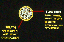
In contrast to STICK welding, a primary benefit of a gas shielded flux cored wire, is the wire's flux is protected by an outer steel or low alloy steel sheath. As mentioned, gas shielded flux cored wires are manufactured as low hydrogen products, however that definition only applies as long as the weld wire's flux quality is made by companies who give a dam and are are concerned about the quality of the wires they daily produce, and of course as long as the wire is sealed in an airtight container that's always stored in a "controlled environment".
The flux in the FCA wires can be easily and quickly be contaminated with moisture, and in most ship yards or weld shops, dampness, humidity and moisture is usually the norm.Some flux cored wire sheaths are made with a straight butt seam, however these seams make it easy for the wire to allow moisture through the seam. Other wires like the the Kobelco wire in the picture on right, may have a seam that is designed with a little more consideration for keeping the flux trapped, and reducing the chance of moisture getting to that flux.
2000: ONE SIMPLE BEST WELD PRACTICE THAT I ALWAYS IMPLEMENTED, DATE - TIME AND TAG THE FCAW WIRE SPOOLS.
Due to the general lack of global flux cored best weld practices, few weld facilities require their welders to Date and Time Tag the new FCAW wire reels utilized. What is normal especially in large weld shops, is once the flux cored wire is removed from it's container, the wires are typically left out in cold, damp or in humid conditions for god knows how long, (it only takes a few hours for moisture to be an issue)..
Note: There are usually major differences in the quality and performance of the flux cored wires from the major different flux cored wire manufacturers. With flux cored wires you typically will get what you pay for, and if it's made in China or Eastern Europe good luck with your lower price wire. I have tested these wires from global wire mfgs for more than three decades, and I found for example that Lincoln Electric in Cleveland had a long struggle with its gas shieded flux cored wire quality / performance, so you can imagine the struggle wire manufactures have in other countries where product quality has another meaning..
Note: My first choice for quality and the best performing flux cored wires, was either an Alloy Rod or Kobellco products and after testing their products I refused to use either Lincoln or Hobart wires, although I did think the Lincoln L50 MIG wire was a good product.
.
A FEW OF THE THINGS THAT INFLUENCE THE FORMATION OF HYDROGEN CRACKS:
[] High strength steels.
[] Restrained parts.[] Stress concentrations.
[] The use of electrodes or wires that are not suited.
[] Weld defects.
[] Large root gaps, plate misalignment, anything that results in excess weld heat and excess stresses.
[] Steel surface contaminates. (moisture - rust - paint - oxides - millscale - lubricant - markers)
[] Lack of control with the required preheat and inter pass temp controls.[] Lack of quality with the wires used.
[] Lack of history and protection for the flux cored wires used.
[] Lack of awareness of the potential for moisture in the weld gas cylinders - or gas pipe utilized.
[] Lack of weld process, technique and best practice knowledge that could help minimize the effects of moisture
WITHOUT BEST PRACTICES & PROCESS CONTROLS, CRACKS ARE BOUND TO HAPPEN.
It's inevitable that on that on that one billion dollar naval vessel,containing high strength steels, that when that vessel leaves the docks, its leaving with thousands of serious weld defects and many hydrogen cracks.
To add to the quality concerns, the hydrogen cracks may be in the weakened weld's Heat Affected Zone locations which run either side of welds that often usually contain lack of fusion, slag inclusions and extensive porosity.
It's easy to minimize the opportunity for hydrogen cracking with gas shielded flux cored and MIG wires..
[] Grind the weld prep surfaces to sound metal, and grind at least 18 mm either side of the weld joints.
[] Only use weld wires made by reputable wire mfgs. (Avoid wires made outside North America). If the wire you use provides excess porosity or worm tracks, get a different wire from another wire mfg.
[] Use cylinders of weld gas that have dip tubes, and ensure the gases are supplied from reputable suppliers who can provide certificates showing moisture content of the cylinders they fill.
[] Especilly if costly NDT is applied or the welds can generate safety concerns, start the job of with a "new box" of weld wire thats been stored in a heated container.
[] Tag date - time the new wire.
[] 100F pre-heat close to the weld area.
[] Use stringer (not weave_ passes. The weld size - mass would be the size of 1/4 fillet.
[] Inform the welder that if they see any weld porosity or worm tracks during the weld, STOP, grind out the defect, check the gas flow, and repalce the wire. (Get a refund for that bad wire).
[] Weld energy and cooling time has a big factor on the formation of hydrogen so do not produce small or thin fast freeze welds that are typical with weaves.
[] Grind - Grind - Grind between passes, ensure all slags, oxides and visable defects removed.
[] Ensure there are no fans, wind or drafts blowing on welded part.
[] Interpass temp min 100F Max 300F.
Note: Ed's flux cored and MIG process control training programs deal with all the process controls and the weld best practices that should be applied for weld defect prevention.
SOMETHING ALL NAVY AND SHIP YARD WELD PERSONNEL WOULD DO WELL TO REMEMBER.
Weld personnel emember, when building any Navy vessel, there will be many wild ocean days, and a failed weld on a ship can have the same consequence as those elusive weapons of mass destruction.
E-mail 2005. Dear Ed. The weld process control data in your Management Engineers book has been great! As I read your book, it seems like you have been inside my brain. We are now breaking away from SMAW and GTAW and i will be implementing Flux Cored and MIG procedures on our pipe / pressure vessel welds. I will keep you informed and thank you for your work and process knowlege.
Matthew Panconi.
Executive Vice President.
Sylvan Piping NJ.
Imperial Oil Pipe Weld Research Project: Ed managing
& testing MIG - flux cored wires on Nat Gas Pipe..
IN 2003, ED MANAGED A PIPE WELD PROCESS RESEARCH PROJECT FOR IMPERIAL OIL, ALBERTA, CANADA, (THE COLD LAKE PIPE WELD PROJECT). THE PURPOSE OF THE PIPE WELDING RESEARCH, TO EVALUATE THE LINCOLN STT MODE VERSUS TRADITIONAL SHORT CIRCUIT FOR THE ROOT AND ALSO COMPARE DIFFERENT MIG, METAL CORED AND FLUX CORED WIRES FOR THE PIPE FILL PASSES.
PIPE MIG WELD WIRES: IF YOU WANT OPTIMUM, STEEL MIG WIRES FOR PIPE ROOT WELDS CHECK OUT AN ESAB OR LINCOLN L50, WIRE VERSUS THE POORER PERFORMING, COMMONLY USED E70S-X K NOVA MIG PIPE WIRES AVAILABLE FROM THYSSEN.
THE THYSSEN MIG WIRE I USED FOR THE COLD LAKE PIPE ROOT RESEARCH PRODUCED A SLUGGISH, FAST FREEZE, SHORT CIRCUIT WELD, A WELD POORLY SUITED FOR ANY PIPE APPLICATION.
DURING THE PIPE WEL AND WELD CONSUMABLES TEST, I ALSO EVALUATED A NUMBER OF METAL CORED WIRES FOR THE PIPE ROOT WELDS, AS I SUSPECTED WITH TRADITIONAL SHORT CIRCUIT TRANSFER THE METAL CORED WIRES PROVIDED NO WELD BENEFITS.FOR THE PIPE RESEARCH PROJECT, I ALSO TRIED E80S- D2 MIG WIRES FOR THE ROOT, THESE HIGHER TENSILE MIG WIRES PRODUCED GOOD WETTING IN THE ROOT WELDS AND WITH THE LINCOLN STT PROCESS, THERE WAS NO ISSUES WITH THE E80S-D2 WIRE.
WITH SHORT CIRCUIT TRANSFER, THE ROOT WELDS WITH THE 80S-D2 WIRES PRODUCED A VERY BENEFICIAL FLAT SURFACE, ALWAYS LESS CONVEX THAN THE TRADITIONAL E70S-X MIG WIRES. KEEP IN MIND THAT THESE HIGH STRENGTH WIRES OFFER LESS DUCTILITY THAT THE E70S-X WIRE SO WHEN WELDING THE PIPE FILL PASSES, THE 80S COULD BE MORE PRONE TO HOT CRACKS IN THE SMALL ROOT WELDS. AT THE TIME OF THESE TESTS I DID NOT HAVE THE TIP TIG PROCESS WHICH WOULD HAVE MADE LIFE A LOT EASIER.NOTE: IF YOU ROTATE YOUR PIPE JOINTS THE BEST PROCESS IS NOT FLUX CORED OR PULSED MIG, IT'S CONVENTIONAL SPRAY TRANSFER.
Ed's one million dollar FCA pipe weld cost reduction, for Imperial Oil Canada
Set the flux cored wire weld voltage so the tip of the flux cored weld wire is as close as
possible to the weld (arc length) without the wire touching the weld and causing weld spatter
After setting the weld wire feed rate,
fine tune the arc length with the weld voltage control.
Confused about European Pipe Weld Specs? You should be.
Gas Shielded Flux Cored Wires.
YOU KNOW IF FEEMA APPROVES SOMETHING. THAT IT'S GOT TO BE SCREWED UP. THE WORLD'S "WORST WELD PROCESS" IS THE SELF SHIELDING FLUX CORED PROCESS. YOU MAY BE SURPRIZED TO FIND THE WELD PROBLEMS WITH THESE CONSUMABLE IN BOTH THE CONSTRUCTION AND AUTO INDUSTRY
HOW DOES A COST COMPETITIVE GLOBAL WELDING INDUSTRY CONTROL IT'S FLUX CORED OR MIG WELDING COSTS. WHEN FEW WELD SUPERVISORS ARE AWARE OF THE OPTIMUM WELD SETTING OR THE WELD DEPOSITION RATE POTENTIAL?
Weld deposition rates may drive weld costs, however in the global welding industry, it's rare to find a weld shop supervisor who is aware of the weld deposition rate they should be attaining for a specific flux cored or a MIG application.
With my unique flux cored and MIG process control programs. all a manager, supervisor, technician or welder has to do is provide a quick glance at any wire feed unit and they will instantly know the weld deposition being delivered and if the optimum weld settings are being utilized.
With the common USA gas shielded flux cored weld wires, be aware that for vertical up, structural / pipe / pressure vessel welds on carbon steels, you can attain a higher, stable weld deposition rate from a Kobelco / ESAB all position, gas shielded flux cored consumable than you can from a similar Lincoln - Hobart - Corex flux cored product?
When evaluating the all position gas shielded flux cored wire electrodes, to attain optimum welds in any position, you must first achieve a stable, small weld droplet transfer. When evaluating all position flux cored wires;
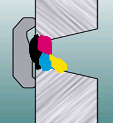
[a] As with the photo on the right, look for erratic large round weld drops that result from large globular weld transfer. This transfer typically occurs when the weld current (wire feed rate) and voltage is typically too low or you simply have purchased poor performing flux cored wires manuafactured likely in China - India or S. America.
The globular weld transfer will provide excess weld spatter, cause arc and weld stability issues, result in lack of weld fusion and destroy the contact tip especially in a pipe weld over head weld position.
[b] Examine how easy the flux cored weld slag can be removed from multi-pass, vee groove welds.
[c] Look at the wire feed range settings and evaluate the low end capability for thin wall applications and examine the maximum weld deposition that can be attained for the common type welds attained. My books and self teaching resources simplify this task and show both optimum wire feed settings and weld deposition rates.
[d] Examine the optimum flux cored settings in which you can control the weld puddle especially in the overhead and vertical up weld positions.
[e] Look at how much weld smoke produced at the high current settings.
[f] Check how frequently you encounter commom flux cored weld defects such as worm tracks and porosity.
[h] Check the quality of the wire winding on the spool and the protection from the flux cored wire package.
Provide MIG or flux cored process control training
and you can instantly make a welding pro.
THE BEST, NORTH AMERICAN, GAS SHIELDED FLUX CORED WIRES.
While I recommend the made in Cleveland Lincoln "L50" MIG wires, I have never recommended the Lincoln gas shielded flux cored products as I found there wires have created many weld issues for me. In their optimum weld parameter range, the all position Lincoln E71T1 wires that I tested, provided erratic weld transfer which suggests a wire chemistry imbalance and also extensive worm tracks resulted. In contrast to the ESAB / Kobelco wires, the Lincoln E71T-1 gas shielded wires also provided a narrower optimum weld parameter range, with less control of low and high amp settings. For the weld shop this means that the Lincoln wire I tested, would provide less weld deposition and less weld fusion potential for vertical and horizontal welds.
Remember with flux cored, the adjustment of the arc length is critical for vertical up weld control.
Volts too high = weld too fluid. Volts too low = weld spatter.
WANT TO SAVE A MILLION ON YOUR NEXT SMAW PIPE LINE PROJECT?
CLICK ON" ED'S REAL WORLD APPLICATIONS".
IN THIS INDUSTRY PROCESS OPINIONS ARE OFTEN CHEAP. There are many engineers involved with pipe, pressure vessel fabrication and cladding that have strong negative opinions on the MIG, pulsed MIG and flux cored weld process, yet few of these engineers will have extensive MIG or flux cored weld process control expertise.
NO THE WHITE HOUSE IS NOT THE GREATEST PLACE FOR A REALITY TV
SHOW. I WOULD DO IT IN THE WELD SHOP IN A SHIP YARD.
IF YOU TOOK THE CULTURE OUT OF THE WELD SHOP, LIFE WOULD BE BORING.
A message from Bubba Baxter Brown Junior the 111. President of the BBBJ111 Oil Pipeline / Platform Inc..
" Boys, for this pipe here weld project, I want yea all to keep the automated and pipe weld equipment costs to a minimum. Ive known many of you since high school and Ive come to the conclusion that we need the ability on this project to keep the weld operation as simple as possible. Now I know that most of you are from Texas, however I want the key weld decision makers in this organization to minimize the "BS". When I ask you had better be ready to provide me with logical justification for the purchase of any sophisticated electronic bells and whistles you feel you need to weld this pipe line.
BBB junior continues. From now on I want my weld team to "ignore weld sales advice" and start making rational weld decisions for your selves. Dam it men, and I use the word men loosely, we need to cut through the BS that surrounds this MIG and flux cored weld process and stop hiring wimp wristed project managers and supervisors who spend most of their days getting advice from salesmen and who believe the only way to weld a pipe is the way we did it in 1960 with a Lincoln E60XX E70XX electrode.
Before the obease Bubba continues with his conversation he feels that he's getting a little too exited, and his blood pressure is getting pretty high. BBB takes a time out and asks his assistant to get him a Budwiser Beer, which in reality is just like having a glass of water. After a few burps;
BBB continues. "You boys take note because this is the bottom line":
[] I want this fabrication organization to be known as a cost affective, dynamic company that consistently delivers optimum weld quality and delivers it's products always on schedule.
[] I want this companie's weld decision makers to have the ability to differentiate between process and equipment bells and whistles and cost effective weld benefits.
[] I want this organization to ensure the weld processes utilized are made simple to operate and the equipment purchased is both logical and durable.
[] FinallyBubba finishes with, "by the way, I will shoot the next guy that tells me "that this is the way we have always done it". I want each engineer and manager in this organization to go home to night, look in the mirror and repeat the following three points.
[1] Buba has made me responsible and accountable for all the weld process decisions and issues daily generated in this organization.
[2] Bubba wants me to do my utmost to establish and maintain Best Weld Practices for this organization and for my sub contractors.
[3] Bubba wants me to ensure that all weld personnel involved in this companies welded products receive the Process Control Training necessary for Process Optimization.
2005: The slow and often painful weld process evolution..
After almost four decades after the development of small diameter, gas shielded flux cored wires by Alloy Rods, we still have weld engineers and managers in the oil, power and chemical industries, who would would rather have their applications welded with stick electrodes (1 - 1.5 lbs/hr) rather than with the superior, weld quality, easier to use, more cost effective flux cored process at 6 - 10 lb/hr.
PIPE WELDS & WELD PROCESS QUALIFIED?
Today, pipe line weld decision makers have many weld process and process combination choices when welding the pipe fill and root passes.
[1] Stick root / stick fill.
[2] Stick root / flux cored fill.
[3] Stick root / pulsed MIG fill.
[4] TIG root / stick fill.
[5] TIG root / TIG fill.
[6] TIG root / pulsed MIG fill.
[7] TIG root / flux cored fill.
[8] TIG root / metal cored fill.
[9] STT root / your choice for fill.
[10] CMT or RMD root / your choice pulsed or FCAW for fill.
[11] Globular MIG, Pulsed MIG for pipe ID and Pulsed MIG and flux cored for fill.2013: For large scale pipe projects, multi-gun mecahanized pulsed MIG is the preferred choice. For manual pipe welds avoid pulsed MIG (lack of fusion see pulsed MIG section). The TIP TIG process should always be given first consideration for pipe applications.
Left photo: Ed was the project Weld Quality Manager during construction of Africa's largest power station built in Nigeria during the 1970s.
Note from Ed. One trip to Nigeria is enough for one life time.
There are always many opinions on the weld process and consumable selection for that pipe or pressure vessel application, yet over the years I have wondered how many people in the Oil - Energy industry are sufficiently "weld process qualified" to make a rational process choice for a pipe root pass when evaluating the Short Circuit, Globular, Spray - STT - CMT - RMD weld transfer modes?
Weld Process Control knowlege is just one click away.
IF CONFIDENT IN YOUR WELD PROCESS KNOWLEGE,
THE FOLLOWING WELD TEST WILL BE A BREEZE.
Weld process control is measured by weld process expertise, would you like to try this fundamental weld process control welding test?
WHEN AN INDUSTRY OR COMPANY SUFFERS FROM WELD PROCESS APATHY OR IS SLOW TO GRASP THE WELD BENEFITS DERIVED FROM UNDERSTANDING BEST WELD PRACTICES & WELD PROCESS CONTROLS, THE WELD DECISION MAKERS WILL OFTEN IMMERSE THEIR HEADS IN THE WELD SHOP SMOKE, BECOME THE COMPANY FIREMAN, SHY AWAY FROM WELD PROCESS CHANGE, NURTURE THEIR RELATIONSHIPS WITH THE LOCAL WELD SALES REP AND IMMERSE THEIR WELD SHOP MANY USELESS WELD CONSUMABLES AND EQUIPMENT WITH OVER PRICED BELLS AND WHISTLES.
2009: FROM MILLER. THE MULTIPURPOSE PIPE WORXPOWER SOURCE:
2009: I have to ask why would anyone waste $13.000.00 on this Miller multi-process power source, or waste $11.000 on the Lincoln STT / Power Wave to do manul pipe welds?. Miller believes that it's so called unique Pipe Worx has multi-process RMD - Pulsed MIG - Stick - FCAW - TIG attributes that benefit the weld shop.
The Miller RMD (Regulated Metal Deposition) process is used for the pipe root. RMD is simply an electronically modified, MIG short circuit transfer only suitable for all position open root pipe welds. Miller also belives it's pulsed MIG program is ideal for all position pipe fill, however many shops who use this process will find unexpected lack of weld fusion from the pulsed welds.
REMEMBER MECHANIZED PULSED MIG PIPE WELDS CAN WITH SPECIAL CONTROLS (SEE PULSED MIG) PROVIDE 100% X-RAY QUALITY. IN CONTRAST MANUAL PULSED MIG WELDS WILL TOO OFTEN PROVIDE LACK OF PIPE WELD FUSION.
It's ironic that with all the bells and whistles on the Miller equipment and the too often useless wave forms on the Lincoln weld equipment, that their over priced multi-purpose weld processes will never attain the weld quality or be as simple to use as the much lower cost TIP TIG process.
Tip Tig is the world's best manual process for pipe shop welds
And the best power source for all position E71T-1 wires
is the lowest cost traditional CV MIG power source?
One of Ed's Process Control Resources.
If you want to establish Best Flux Cored Weld Practices and
Weld Process Control Training, you may want to consider.
Ed's UNIQUE BOOKS CD TRAINING RESOURCES.
BEFORE YOU RUN THE FLUX CORED PIPE FILL PASSES YOU NEED TO MAKE A DECISION ABOUT THE ROOT, IF YOU DON'T HAVE THE LINCOLN STT OR MILLER RMD FOR YOUR PIPE ROOT WELDS, AND YOU HAVE A REGULAR, MUCH LOWER COST, CV MIG POWER SOURCE, CONSIDER THE FOLLOWING...
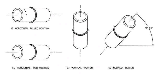
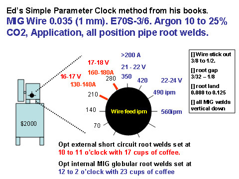
PIPE 1G ROOTS: For the external, "1G" horizontal rolled pipe root welds, set the a traditional low cost, ($2000) CV MIG process for "short circuit transfer" with an 0.035 (1 mm) wire, argon 20 - 25% CO2.
For the root short circuit weld, rotate the ant-clock wise with the gun a 2 pm. You are welding in the vertical down weld position using the drag technique. For the root prep provide an 0.080 land with a 0.100 - 0.125 root gap. Set the short circuit wire feed rate at 250 to 300 ipm (around
11 o'clock wire feed control position), with 17 to 18 volts. Let the
contact tip stick outside the gun nozzle. Start in the middle of a ground roo tack, (tacks should be 25 mm long and ground so the are approx
1.6 mm thick). Position the weld wire in the center of the pipe root gap and rotate the pipe anti-clock wise. Use the drag technique with the weld wire in the center of the root gap, short circuiting on the leading edge of the fast freeze weld puddle. With the root weld tie-ins, reduce the wire stick out to increase the weld energy. No root weld weaves are necessary for the root pass as long as the root gap dimensions are maintained. This traditional, CV low cost MIG process is simple to operate and always provides great results for the 1G pipe roots .Note: Info like the above is available in my MIG process control training resources.
Pipe 5G ROOTS: For a mechanized rotating "internal 5G root weld", common with large pipe line welds, the root weld settings can be carried out with either MIG short circuit or globular mode, welding vertical down. For the globular MIG mode, use an 0.035 wire, a gas mix of 25% CO2 and a wire feed rate of of 400 to 500 IPM, (one to two o'clock) with 20 - 24 volts.
For the external root use the short circuit mode with wire feed at 250 inch/min 17 volts, use the pipe root gaps and edge prep dimensions mentioned for the 1G position. At the root overhead, 5 to 7 o'clock positions use an aggressive weave with a slight back hand to avoid the wire running through the root gap. For the 1 to 5 and 11 to 7 o'clock positions weld vert down the same technique as mentioned for 1G. For the top of the pipe at the 11 to 1 o'clock position use the drag (wire back to weld pool) with slight weave.
Photo: It took Ed 30 minutes to teach Jesse 11 years old Jesses on how put a root pass in a pipe. Using short circuit or the newer, modified MIG modes for the root welds requires minimal manual weld skills and typically will attain root weld speeds of approx. 15 ipm. As all pipe shops are aware it's important to maintain consistent root dimensions and good pipe alignment.
As root pass welds can be made with TIG, SMAW, pulsed MIG or modified short circuit MIG equipment, and a seperate weld process or consumable is required for the fill, perhaps its time to look at one process that provides the best weld quality for for both the root and tfill passes. Check out TIP TIG.
As we head in to 2013, I hope the new weld generation will quickly evaluate and embrace the world's best, manual pipe welding process which was developed in Austria. My partner Tom OMalley and I introduced this important process to North America and Australia. When you have a moment, please take a look at the TIP TIG weld process at www.tiptigusa.com.
June 12. 2009. Welcome to the first real practical advance in manual - automated pipe - vessel welding and cladding process technology, the process is called." TIP TIG"
Above, Sieman's P91 pipe joints used to be manually welded with traditional TIG and SMAW, and the weld times was approx. 3 hours per-joint. The welds you see in the pictures are now made with the TIP TIG process and the defect free welds took less than 50 minutes per-joint. In contrast to traditional manual TIG - pulsed MIG and Flux Cored process, the TIP TIG process is easier to use and will always produces superior weld quality with the lowest possible weld heat and that means superior metallurgical properties.
Ed introduce Tip TiG to the USA in 2009. In the last six decades this is the
first real practical advance in manual pipe welding technology"
These P91 pipe joints used to be welded with traditional TIG and the weld time was 3 - 4 hours per-joint. The welds you see in the pictures are now made with the TIP TIG process and the defect free welds took 50 minutes per-joint. In contrast to traditional manual TIG - MIG and Flux Cored, the TIP TIG process is easier to use and always produces superior weld quality with the lowest possible weld heat. The TIP TIG process will provide Advanced TIG pipe welds at highly cost effective pulsed MIG deposition rates.
A sad Ed Joke:
Check your FCAW Process expertise.
See how you do with the Flux Cored Quiz.
Weld Question from UK.
Hi Ed I love the site, it's a breath of fresh air. My name is Mick Brennan. I work in the UK and I have been involved with the welding offshore and cross country pipelines for close to 40 years. Much of my time is spent using the Mechanized MIG Process. Some of the ID MIG welds have involved combination Internal clamping and complex ID Weld Machines. This is a fine process but it can be very costly as the Pipe Ends require costly Internal Bevels and a Narrow Gap preparation on the outside. The money saved on less deposited metal and less welders gets eaten up with this unique Bevel Design and the use of a costly Internal Welder. Using this equipment on shorter pipelines < 20 Miles becomes uneconomical as the pipe weld equipment is usually rented in and a mob and demob fee erodes the potential profit.
Regards Mick Brennan. UK.
Ed's Answer:
INTERNAL PIPE ROOT WELDS: Mick as you know, controlled, internal, pipe weld roots can be made with 0.035 MIG wires with the correct wire feed stickouts of 3/4 to 1''. I recognize your long wire stick out reduces the root weld current and enables higher wire feed rates, but who gives a dam if a pipe root is done in 3 minutes or six minutes? What is important is doing the root weld with the best possible weld controll and that simply does not happen with a 3" wire stick out. The ID roots can be done with the recommended wire stick out and a short circuit wire feed rate of 250 to 300 IPM with 17 to 19 volts. Also controlled globular transfer wire feed 350 to 450 ipm with, 20 to 23 volts. The MIG settings you provide, with a long wire stick out, WF 500 ipm - 23.5 volts are simply globular transfer.
20013: EXTERNAL PIPE ROOT WELDS: The MIG STT - RMD and CMT modes are well suited to external open root welds as long as the root gaps are controlled and specified pipe alignment dimensions are maintained.. The settings with these weld modes which typically utilize 0.045 wires are similar to the optimum short circuit wire feed rates and voltages provided above for the 0.035 wires.
For five decades engineers in the oil and energy industries gave MIG a bad name, and on many pipe weld applications the reasons were never logical.
MANAGERS PLEASE NOTE. WHEN YOU "ROTATE" A STEEL OR ALLOY STEEL PIPE, USING THE 60 YEAR OLD MIG SHORT CIRCUIT MODE, YOU CAN TRAIN IN LESS THAN ONE HOUR, A PERSON WHO HAS NEVER WELDED, TO PRODUCE OPTIMUM ROOT WELDS THAT WILL MEET ANY CODE REQUIREMENTS.
Modified Short Circuit versus Traditional Short Circuit.
Note: The above picture is a a pipe root weld process evaluation. I managed and performed this evaluation for a contract I recieved from Imperial Oil, (Cold Lake Canada project). With this project I evaluated the STT and traditional SC MIG mode for the roots and various flux cored wires for the fill passes. The welds carried out by Imperial Oil Union contract welders.
The STT process is little more than a low parameter PULSED MODE " that transfers low energy weld drops across the root arc gap bridging the root gap. Without electronics you could set a controlled globular made which would fuction but with less control and much more spatter. As short circuits are rare with STT and globular this eliminates wire from driving through the root gap and sticking to the inside pf the pipe. STT was in the above photo used by the welder on the left. The traditional MIG short circuit transfer mode when set correctly (noted by the small amount of spatter), was used by the welder on right.
ED WELDING THE 16 INCH, NATURAL GAS PIPE AT 5 O'CLOCK. WITH A PAIN IN HIS SHOULDER AND NECK. HE WAS WISHING IT WAS
5 O'CLOCK AND TIME FOR THAT DAILY DIET OF A PINT OF GUINESS.
The only problem area I had with all position, external MIG pipe root welds which were made with the traditional MIG short circuit mode and 0.035 wire, was found at the 5 - 7 o'clock root area of the pipe. At this position, during the short circuits occasionaly a piece of the weld wire would go through the root and stick inside the pipe. The 5 - 7 o'clock pipe positions would also result in root welds with a slight root weld suck back . The bottom line, it's difficult to control the short circuit root weld quality in the over head area. Note:This root area required another short circuit technique which I have now figured out. Both the MIG short circuit and all position gas shielded flux cored process can be used with argon 20-25% CO2 gas, low cost generators with CV adapters or with low cost CV MIG equipment.
MIG and Pipe Root Tacks.
If on your pipe application, the required pipe root dimensions and edge preperation cannot be maintained, the root pass should be made with the SMAW, TIG or TIP TIG.
ROOT TACK LOGIC: F or the a MIG root pipe prep and the short circuit process, use an 0.070 - 0.080 land and a 3 mm root gap. Note for those that normallly use a feathered edge, you are using weld practices associated with the SMAW process which has nothing in common with MIG. The 0.070 - 0.080 land adds base metal to the filler which adds metal to the root reducing root center line cracks and an increased root throat also enables the next fill pass to provide more weld energy. Remember most pipe weld defects are found in the first and second fill pass over the root.
With the short circuit (SC) or the other MIG modes used for the root. Using an 0.035 (1mm) wire, place three or four weld tacks 30 - 40mm in length, then feather the total tack length so the tacks are about 1.8 mm thick. Start the root weld in the center of one tack and finish in the middle of another tack. Then with a grinder blend the two tacks just welded back to 1.8 mm thick. Continue with the same practices.
(1) BENEFIT OF ROOT LAND: If the root pass filler metal is stronger than the base pipe metal, the filler weld dilution with the root land will lower the root weld strength and therefore provide less weld shrinkage stresses. In this situation the root weld ductility will typically increase reducing the potential for hot weld cracking in the root..
(2) BENEFIT OF ROOT LAND: The land on the pipe bevel alows a solid surface for the root weld to attach itself in a uniform manner. The land as mentioned adds to the root depth. This enables a higher energy fill pass to take place without concern for root weld burn through.
When the gas shielded flux cored consumables are selected for the pipe "fill" passes, pipe line welding companies should examine closely the need for costly, complex automated pipe weld units, versus a simple automated, carriage and CV generator for the gas shielded flux cored pipe fill passes.
FOR SMALL PIPE LINE PROJECTS IT PAYS TO KEEP IT SIMPLE AND COST EFFECTIVE:
Take a look at your process and equipment choices. Consider a $130 to $200K, complex, automated, multi-torch, pulsed MIG pipe line weld package, or will a simple to operate mechanized, carriage / track with a CC- CV generator and all position gas shielded flux cored wires for approx. $30,000 do the job as shown on the right?.
The flux cored wires, two simple weld procedures and a low cost generator (with CV mode) with the low cost mechanized carriage package could provide the following benefits;
[a] When manual or automated welding on pipe lines using flux cored wires, one volt / wire feed amp weld setting is all that will be required for the pipe fill passes and one setting for the cap. The weld speed and weld weave width will of course change.
Note: When pipe weld operators use many flux cored or MIG "weld parameter combinations" for multi-pass, pipe fill welds, it's an indication the people who set the equipment are typically not in control of the welding process.
[b] The simplicity of the two simple weld controls (volts - wire feed) used with the flux cored process, allows the manual or automated pipe weld operators "easy control and weld adjustment of the weld process" To optimize this pipe welding process I recommend my MIG - Flux Cored weld process control resources.
[c] The flux cored process provides greater weld fusion than any pulsed MIG mode, it will also provide less porosity potential and require less welding skills. The down side is the slag removal, the upside is with a good wire and the correct parameters the slag should remove easy.
[d] For the Flux Cored pipe fill passes, a simple low cost mechanized carriage attached to the track that straddles the pipe would sell for $10K $20K. The weld carriage should have the weld controls necessary for weld height adjustmant, weld speed and weld weave controls. The weld gun or two weld guns operating weither side of the pipe (depositing 20 lb/hr) would be hooked up to a traditional, field wire feeders that would be attached to CC / CV generators.
FOR ALMOST 40 YEARS FLUX CORED HAS BEEN A WINNER, IT'S JUST THAT MANY IN THE WELDING INDUSTRY FAILED AND STILL TODAY, FAIL TO RECOGNIZE THE FLUX CORED PROCESS POTENTIAL...
Note: If optimum flux cored consumables are selected and the flux cored weld data is correctly applied, as the following photo indicates, all the welds will be made with one set of weld parameters with changes only for the weave data. If the weld data is correct the pipe weld slag should fall off almost without assistance.
When Ed makes Flux Cored Pipe welds the flux peels off.
If welding the pipe line root weld on the "inside" of the pipe, the traditional low cost, CV, MIG equipment or a CV adapter on a CC generator may be used with a MIG wire using;[1] a high short circuit setting,
[2] a controlled low globular setting,
[3] a low spray transfer setting with less than normal spray transfer weld volts.
Note: For 1 to 3, the 0.035 (1 mm) E70S-3 wire with argon 15 to 25% CO2, will provide the greatest control in open root pass welds. Use Ed's MIG process control resouces for optimum data
Ed's "Clock Method" process control - best practices simplifies MIG and Flux Cored process control training. With this Nat Gas pipe, in less than one hour, Ed taught 11 year old Jessie how to optimize the MIG weld settings and produce a code quality root welds..
1999: The following statement is one many highly skilled SMAW pipe line welders will not want to hear, however like it or not, it's weld reality and different processes when understood enable different weld opportunities. Using the available MIG weld transfer modes for a pipe root, a none-welding individual who is drug free, has good vision, good dexterity and the "right attitude" can be trained in no more than a day to weld an all position pipe root welds that will meet any pipe code weld requirement.
I would also like welders, technicians and engineers to be aware that any professional weld decision maker is much more than the sum of his skills. A good weld professional will combine their skills with weld process controls and best practices knowledge and can apply that expertise to any of the common weld processes and consumables used throughout the global welding industry..
Lincoln Invertec STT. Featuring the Surface Tension Transfer (STT) Process
The STT II power source, combines high frequency inverter technology that produces low pulsed MIG parameters suited to welding a gap. This process provides no real world weld benefits to most other common steel applications making this power source a costly, piece of equipment to have sitting on the floor of a weld shop.
2006: Note: Once competitive MIG power source manufactures wake up, they will develop similar pulsed arc characteristics / parameters to STT from the available pulsed weld technology and create a pulsed program suited to pipe root welds.
If you are using the STT for a root weld. You typically providel a root gap of 1/16 to 3/16. Note 3/32 to 1/8 is optimum. I would recommend 1.6 . 1.8 mm land. Remember the land adds metal to the root increasing the root weld depth and often reducing root cracking potential.
STT PIPE ROOT.
THE PULSED PARAMETERS:
With that 0.045 (1.2 mm), E70S-3 wire and argon 10 to 20% CO2, set the STT parameters in the following approx. range.
Pulsed Peak 320 - 360 amps, (Opt Start 325A)
Pulsed Back Ground. 40 - 60 amps, (Opt Start 45A)
Pulsed Wire Feed 110 - 160 ipm. Opt start 120 - 140 IPM. (same as short circuit with 045 wire)
Note: The optimum wire feed and average modified STT current for the pipe root is also the same as the optimum short circuit wire feed range and weld current for the same application. To anyone who understands the relationship between gaps, weld current and wire feed rates, no surprise there.
2004: You highly skiller SMAW pipe welders, rather than resist the inevitable cost effective process changes for pipe line welds, I would recommend you reach out and embrace the manual / automated modified pulsed / short circuit transfer modes along with the flux cored process and strive to become expert "manual or automated pipe line weld technicians".
E-Mail. Feb 2004. Mr. Ed Craig:
I have been welding for ten years but have never, like you say,really known or understood the optimum MIG or Flux Cored weld parameter settings. What would be the optimum manual flux cored weld parameter settings using .035 wire welding 6" schedule 180 pipe in the 6G position on carbon steel? I have never welded with FCAW to make a root weld in a pipe. I need to take a test on Monday and sure could use this information. I think your book " Gas Metal Arc and Flux Cored Welding Parameters " is the book I need to have and do plan to buy it. Thanks for your help and Ed thanks for your website.
Sincerely,
Larry Fritsche
Ed's reply. I must get two letters or phone calls like this every week. Two days before the welder takes a test he suddenly realizes he will not know where to set the optimum MIG or flux cored weld parameters for his critical pipe or fabrication weld test. It seems to be a common theme the southern states that when the welders take a pipe or tank weld test, the process ignorant supervisors and engineers may demand that the welders use flux cored for the pipe root welds.
For those process ignorant individuals who are making welders lifes impossible. you do not use flux cored for the root welds. and if you want to know why read the following book.
I WOULD ENCOURAGE ANYONE WHO MAKES A LIVING OUT OF MIG OR FLUX CORED WELDING, TO INVEST IN A WELD PROCESS CONTROL - BEST PRACTICE, SELF TEACHING / TRAINING RESOURCE SO THAT THEY CAN CONTRIBUTE TO THEIR COMPANY & INVEST IN THEIR CAREER.
For those of you that feel you have mastered the single wire MIG process, try this fundamental MIG Test?. If you use flux cored, try this Flux Cored Tests. Those that truly understand the weld processes they work with would have no trouble setting this 8 wires pipe application, running these four Fronius twin wire units that provide an average weld deposition rate of 55 - 65 lbs/hr. For those that want to improve their process expertise, I would recommend my self teaching MIG manual or automated weld process control resources .
Weld process rationalization and weld process controls have to be the responsibility of "qualified managers and engineers".It's not uncommon in the pipe and fabrication industry to find the following:
[1] Managers who believe they can optimize their welds by placing engineers in control who have no practical weld process control experiences with the MIG or flux cored process and equipment utilized.
[2] Managers who stay behind glass walls, resist change and adopt a "hands off management approach" to weld quality production and cost issues.
[3] Managers engineers and weld decision makers who let welders or maintenance personnel make "unqualified" weld process decisions.
[4] Managers who are often rely on or are influenced by "weld marketing and weld salesmanship".
[5] Managers who do not taken advantage of the weld processes and consumables that actually provide real weld quality and cost benefits.[6] Managers who believe that a discussion on weld costs means talking about reducing the cost of the MIG wire or gas.
HOW LONG SHOULD IT TAKE FOR AN INDUSTRY TO UNDERSATND THE IMPORTANCE OF PROCESS CONTROLS AND THE IMPLEMENTATION OF BEST WELD PRACTICES?
IT WAS DURING 1950. THE LOCATION 30 MILES NORTH OF HOUSTON TEXAS. WHILE PIPE WELDING USING HIS 6010 ELECTRODES, RIP VAN SMITH, A 40 YEAR OLD, EXPERIENCED PIPE WELDER DECIDED TO HAVE A NAP IN THE 48 INCH PIPE. WHILE RIP SLEPT THE PIPE WAS SEALED.
Like many Texans, RIP had amazing powers and fifty years later RIP woke up from his oil immersed deep sleep. The unique chemicals inside the pipe had put RIP into a deep coma and not allowed RIP to age. After crawling along the pipe for a 100 miles, RIP found a maintenance access hole. RIP crawled out of the hole and his first stop was Buba'sBarbecue Bar where he purchased a Barbecue triple Burger, extra bacon and washed it down two cases of water whin in reality was Bud Weiser.
After a short nap and a long bath, RIP decided to apply for a pipe line welder position on a new, natural gas pipeline that was running straight through the primary school in the center of down town Houston. Wearing a new Harley tee shirt, recently stained with Buba's famous barercue sauce RIP took his newly aquired Cadilac out to the pipe site office.
As a fellow Texan, the pipe site weld supervisor was impressed with RIP as he pulled out his brand new leather gloves and shield. With the aid of his new 10 inch bowie knife, RIP with a single strike then pierced opened the metal lid container of the E6010 electrodes.
RIP smiled as he held the electrode under his nose and sniffed the sweet smell of his next pay check. With a flick of his wrist he inserted the electrode into the holder and his heart never missed a beat as he commenced to produce a great vertical down welds on the 24 inch pipe.RIP quickly completed the pipe test and the pleased supervisor hired him on the spot. That night in celebration, RIP made mad passionate love to Mary Lou Ellen, a waitress he met at Bubba's. Being a Texan RIP made mad passionate love that lasted eight hours, as Mary Lou lay in a state of exhaustion, RIP leaned back on the pillow, lit a long Cuban cigar and said out loud "life don't get better than this"
The moral of this story I wrote in the 1990s is change does not come easy in the weld industry, and there are few industries that today complete it's fundamental manufacturing tasks the same way they did 50 years ago? I hope the present day managers, welders, technicians and engineers in the pipe and pressure vessel industry will be more open minded to the practical, cost effective weld process changes that can improve both their weld quality and productivity. For gods sake visit www.tiptigusa.com
WHILE RARELY INTERESTED IN BEST WELD PRACTICES - PROCESS CONTROLS, THE WELD INDUSTRY LOVES BEING GUIDED BY "WELD CODES" WHICH ARE OFTEN WRITTEN AND INFLUENCED BY THOSE THAT MARKET WELD EQUIPMENT AND CONSUMABLES. ALSO IT DOES NOT HELP WHEN THIS INDUSTRY DECIDES IT'S WELD INSPECTION PERSONNEL WILL BE MORE QUALIFIED TO FIND, RATHER THAN TO PREVENT WELD DEFECTS.
Weld decision makers often look to weld codes to provide practical, pipe welding advice and recommendations. The weld reality is the weld sections of many weld codes have been written by weld code committee individuals who's strength may not be in the weld processes under discussion.
Some of the major weld code committees in North America are likely to have individuals that are more interested in marketing their companies weld products than they are in writing meaningful, logical weld spec data. Other committee members would benefit if they spent a little more time behind a welding shield before they make their flux cored or MIG weld comments.
50 YEARS AFTER THE INTRODUCTION OF THE "MIG PROCESS", AND 30 YEARS AFTER THE INTRODUCTION OF FLUX CORED ELECTRODES, THE NEWLY REVISED 03/2001 "AP1 CODE 582" STATES THE FOLLOWING ABOUT MIG AND FCAW PIPE WELDING.API. 5.2.3 Pulsed Gas Metal Arc Welding (GMAW-P. The pulsed process may be used for any material thickness. Commentary: Whenever the welding system is changed or the settings on existing equipment are "significantly altered", the fabricator should verify weld properties. The extent of verification or testing should be as agreed between the purchaser and fabricator.
PULSED MIG AND WELD PARAMETER REALITY.
In contrast to the traditional, simple, two weld parameter MIG or flux cored weld processes, there are many weld parameter essential variables that can be readily changed with the pulsed mode. The API code warns against a "significant change" in a pulsed weld settings. What is "significant" weld parameter change?
Keep in mind that at best the pulsed process will only provide marginal weld fusion on vertical up welds on part thickness >6 mm. From my weld process perspective, "a minor pulsed parameter change" can have a significant impact on side wall weld fusion. It's an ironic fact that few weld decision makers or welders understand the influence of the pulsed variables, wall thickness and weld fusion potential.
In that MIG and flux cored pipe weld shop, or out on that pipe line being built, you will find the majority of weld personnel do not fully understand the MIG and flux cored process. And with those applications using pulsed MIG, few weld personnel will understand the influence or the relationship of the pulsed MIG wire feed rates, the weld speeds, voltages, pulsed frequency or peak and back ground current on the MIG arc plasma and resulting weld fusion potential.
WHEN YOU CONSIDER PULSED MIG RATHER THAN FLUX CORED OR TIP TIG for your pipe welds, with all the pulsed variables in a pipe shop who in the shop is going to determine what a significant weld parameter change is?
While on the subject of pulsed, most codes do not address "mechanized versus manual" pulsed and traditional MIG weld inconsistencies".
When a code stipulates that a fusion sensitive weld process like pulsed MIG is OK for any pipe thickness, the code is sending the message that this process is recommended for both "manual and mechanized" welds.
Controlled weld speeds, fixed arc length and a controlled mechanized weld weave have a lot to do with the success of MIG weld using any mode of weld transfer. However you can be sure the traditional "manual weld weave inconsistency" would make the pulsed process a poor choice for pipe fill welds in contrast to the superior weld fusion, gas shielded all position flux cored electrodes.
ANOTHER SECTION OF THE CODE.
API. 5.2.2 Short Circuiting Gas Metal Arc Welding (GMAW-S).
The use of GMAW-S shall be limited to the following conditions:
a]. The short circuit process shall not be used for branch connections or socket welds.
(What if there is a good size root to fill in?)
b]. For vertical welding, the root pass and second pass progression for a material of any thickness may be either uphill or "downhill".
(Have you tried uphill with short circuit?, if so you would not recommend it.)
c]. The fill and cap pass for butt or fillet welds may be welded With this process provided the thickness of any member does not exceed 3/8 in. (9.5 mm) and vertical welding is performed with uphill progression.
(Any short circuit welds made uphill on parts over 3/16 >5 mm are sure to end up with inconsistent weld fusion)
d]. What about the weld gas? The API code does not spell out the MIG gas mix that must be used with the short circuit process or pulsed on pipe welds. Use short circuit with argon <10% CO2 and you can weld in any position and almost guarantee lack of fusion on any parts > 1/8 (>3 mm), (none gap welds).
e]. Why is it that the API code will stipulate where a process can be used but will not stipulate a simple thing like weld parameter limitations for that consumable or process?
(Is it possible the code committee are not aware of this data)?
Finally the API code makes no mention of the higher energy MIG globular or spray transfer modes, does that mean they can or cannot be used. Spray transfer can be an excellent method for a rotated hot fill pipe pass and globular is great for ID roots or hot pass welds.
To repeat an important point .
IF A CODE DOES NOT OR CANNOT PROVIDE THE COMPLETE, FUNDAMENTAL REQUIREMENTS OF A WELD PROCESS RECOMMENDATION, THE WELD REALITY IS THAT CODE SHOULD PROVIDE NO WELD RECOMMENDATIONS OR WELD RESTRICTIONS.
WELD CODES SHOULD PRIMARILY BE CONCERNED THAT WELDS ARE CORRECTLY PRE-QUALIFIED AND CONCERNED WITH THE "CONDITION OF THE FINISHED WELD PRODUCT".
2007: I REALIZE THE IMPORTANCE OF THE PIPE AND PRESSURE VESSEL WELD CODES AND THEIR CONTRIBUTIONS. MY POINT IS HOPEFULLY THAT THE NEXT GENERATION OF WELD CODE / SPEC REVISIONISTS WILL SEE THAT THEIR MIG AND FLUX CORED WELD DATA RECOMMENDATIONS DOES NOT GENERATE THE PROCESS CONFUSION THAT THEIR PREDECESSORS HAVE GENERATED.
Question: Flux Cored Pipe Weld.
Ed here in Canada we are welding a 4 in. A335-P22 pipe to A234-WP22 pipe. We are using a E-91T1-B2 0.045 in. dia. Gas-shielded, flux-cored wire with a 75 Ar - 25 CO2 gas mix. We preheat the pipes to 400° F and do not exceed 550° F for the inter-pass weld temperature. The flux-cored weld current range is from 150 - 225 A. Voltage ranges from 24-29. The supervisor says all his welders have experienced massive worm tracks in the center of the weld bead usually on the cap pass. Yet it doesn't happen on every weld. I told the supervisor to reduce the weld voltage and this seemed to fix the problems. Could you explain why?
However even with quality flux cored consumables the moisture can get into the wire flux due to inadequate weld wire storage or from no protection for the wire when it's out in the shop.Take note of the flux-cored wire manufacturers storage and baking recommendations.
The reason you see the common worm track weld problem in the pipe weld cap pass, is that this weld pass is typically the one with the least weld depth and therefore, has the fastest weld freeze, providing the opportunity for trapping porosity.
Using a slightly longer wire stick out will preheat the weld wire and this sometimes helps. I suggest you use the highest possible weld current, slow down weld travel rate, and increase the weld depth. Turning down the voltage, which is reducing weld energy, is not likely to help unless you end up with a more convex weld — a weld with increased weld depth.
IF YOU ARE LOOKING FOR RESOURCES THAT WILL ALLOW YOU TO INSTANTLY SET THE WIRE FEED AND VOLTAGE CONTROLS FOR ANY GAS SHIELDED FLUX CORED WELD CLICK HERE.
Question: FLUX CORE WIRE SIZES:
Ed we will be welding various diameter stainless / steel pipes in all weld positions, some welders like 1/16 and other welders like 0.052, apart from welder preference is there a logical approach to the selection of an optimum wire diameter.Ed's Answer. Current compatibility with the part thickness and the weld deposition rate attained is what drives the selection of the correct size weld consumable. For pipes with a wall thickness < 1/2, without question the 0.045 1.2 mm gas shielded, all position flux cored wire welding in the 140 to 220 amp range 24 - 26 volts provides welders with the greatest control of the weld puddle particularly in the overhead position. For pipes with wall thickness > 1/2 and diameter consider the 0.052 but keep in mind the 0.045 is always easier to use.
Question: FLUX CORED DRIVE ROLL GROOVES:
Ed I believe you need different guide rolls for different MIG wire and flux cored types, what's recommended?
JH. Manchester UK
Ed's Answer:
[] For solid hard MIG wires use a vee groove built for the wire OD.
[] For flux core wires use a vee groove with at least on roll providing a knurled surface to improve the grip. Watch you do not apply too much drive roll pressure to these wires.
[] For aluminum MIG wires a U groove with smooth surface again don use excess drive roll pressure. With aluminum ensure minimum gaps between the inlet, drive rolls and outlet guides to avoid buckling. If using a regular MIG gun use a hard plastic liner and a maximum gun length of 10 feet.
Question. FLUX CORED TECHNIQUE:
Ed, when welding fillet welds with the E70T-1 gas shielded wires > 1/16 (>1.6MM) do we push or pull the gun?
Answer. If using the <1/16 (<1.6 mm) wires and welding fillet welds you can push or pull, however I would use back hand for all fillet welds with all flux cored weld wire sizes.
THE SELECTION OF FLUX CORED WIRE TYPE:
In many weld shops the first choice FCAW consumable is the "all position E71T-1 wire. This wire is not the best choice if many of the welds are made on steels > 7 mm and the welds are made in the flat and horizontal weld positions. On these welds, in contrast to the E71T-1 wires, a 1/16, (1.6mm) E70T-1, Basic Slag wire would provide a more stable, higher weld parameter range. The welds would result in a superior weld surface, provide more deoxidizers (less porosity) and provide a thicker, slower freeze weld slag that should result in superior weld surface that would contrast to the irregular pock marked weld surface from the E71T-1 wires. Those E71T-1 wires are ideally suited to Vertical / Horizontal welds, and that's the best place to use them.
Note: For those of you who are using metal cored wires on your steel weld applications, please note after evaluating these products for decades I find that they offer no real world weld benefits for the majority of applications in which they are used..
LARGE FLUX CORED WELDS, AND THOSE WELD CRACKS
Ed my company welds with 3/32, E70T-1 gas shielded flux cored wires. The manual welds are single pass fillet welds from 3/8 to one inch. The welds are made on parts in which many welds are concentrated in a small area. The welds are made in positioners and made in the flat weld positions. The typical flux cored weld parameters are 400 to 500 amps and 30 to 32 volts. The carbon steel parts we weld vary from 6 to 50 mm and are used in heavy duty construction equipment. The parts are subject to excessive variables loads. In the past month we have had extensive field weld cracks. The cracks are typically in the weld's heat affected zones. Is this low hydrogen cracking?
Hydrogen may have an influence however the weld procedures used are likely the real root cause. With many weld shops managers there is a common point of view that when it comes to welds "bigger is better"
Large, > 5/16 "single pass" fillet welds require "slow manual weld speeds" of 4 to 8 ipm is typical and 3/32 wires will use weld current up to 500 amps with 30 volts. These parameters can result in abnormal weld heat build up in theparts welded. The high weld heat can be further influenced by possible lack of interpass temperature controls. Excess weld heat can cause excess grain elongation in the parts heat affected zones and welds, weakening the load bearing ability of the steel.
HOW MUCH WELD HEAT IS ENOUGH?
(joules = volts x amps x 60 divide by weld travel speed)Compare the weld joules heat input generated by the flux cored wires and controlled MIG and flux cored welds.
Typical MIG and flux cored welds should be made with a weld joules input of approx. 20.000 to 40.000 joules per inch.
When single weld passes larger than 5/16 are made with large consumables requiring high weld current, the resulting weld joules per-inch can be in the 100.000 to 200.000 range. When more than 60.000 joules per inch are attained in a weld, apart from a potential reduction in the steels mechanical properties, the wire chemistry and weld mechanical properties can also be negatively influenced by excess weld heat which can result in vaporization / reduction of critical weld alloys.
FOR MOST MIG AND FLUX CORED APPLICATIONS. IT'S LOGICAL TO LIMIT THE SIZE OF THE
HORIZONTAL SINGLE PASS MIG AND FLUX FILLET WELD, TO 5/16, 8mm.
Use logical size weld consumables that enable lower weld current with good weld deposition rates . Most important is remember weld speed are limited by the the size of the fillet welds, this is key in dramatically reducing weld heat input.
For flat and horizontal fillet welds on steels with mill scale, the world's most effective flux cored weld consumable size is the 1/16 - 1.6 mm, type E70T-1. With this wire and a single pass limit of 5/16 , the weld operator would weld with approx. 320 to 380 amps, (average 14 lb/hr) x 28 volts x 60 at an average weld speed of around 12 ipm resulting in approx. 50.000 joules per inch. For those concerned with weld production, remember the smaller weld wires and welds enable greater weld control and approx. two hundred percent faster weld speeds than that attained with the 3/32 wires. Also smaller weld sizes and multi-pass welds offer the unique benefits of weld temper beads. Typically the multipass welds when made in weld heat controlled conditions will provide a stress relieve and beneficial grain refinement.LOGICAL INTERPASS TEMPERATURE WELD CONTROLS?
On any steel structure subject to excess weld heat a little welding common sense goes a long way. Interpass temp controls are necessary to control the weld heat build up in both the welds and parts. I would recommend for the low carbon steels that require multi-weld passes a max. interpass temperature of 350 to 400F. The weld temperature should be taken within one inch from the weld edge.
WELD BENEFITS FROM 1/6 (1.6mm) FCAW WIRES:In contrast to the 3/32 wires:
[A] The 1/16 flux cored wire enables both the push (forehand) and back hand techniques allowing for superior weld control. In contrast the 3/32 wire allows only the back hand technique which is required to stop the fluid weld puddle passing the weld wire.
[B] The 1/16 wire can provide high deposition welds with the benefit of lower weld current, something that benefits both the welders and parts.
[C] The 1/16 wire provides superior control of the weld puddle which is especially important to 5/16 "horizontal" fillet welds.
[D] The 1/16 wire provides flexibility for the variable steel thickness sizes > 6 mm found throughout the plant.
[E] The 1/16 wire reduces weld smoke, weld undercut and weld spatter potential.
Visit most global ship yards and you will see that the most common MIG power source is an Inverter, yet these over priced power sources are the worst possible MIG weld equipment choices for welding flux cored welds on any type of sea going naval vessels. The reasons are in Ed's flux cored training resources.
SEE HOW MANAGERS - ENGINEERS - SUPERVISORS WITH PROCESS CONTROL - BEST PRACTICE
EXPERTISE CAN SAVE MILLIONS ON LARGE WELD PROJECTS:
See how you do with the
E71T-1 flux cored weld test.
[] The root cause of flux cored weld porosity and worm tracks.
[] The root cause of flux cored cracks.
[] Repairig armour plate with flux cored.
[] Best way to test flux cored wires and much more, visit
More Flux Cored Data, Part 2.