|
|
Welcome to the world's largest web site on MIG , Flux Cored and TIG. Weld Process Controls & Best Weld Practices. To get to the root cause of GMAW (MIG) & Flux Cored (FCAW) weld issues, requires Weld Process Control - Best Practice Expertise, & lots of Weld Reality. The site provides the MIG - Flux Cored and TIG weld information and data required to attain the highest possible manual and robot weld quality, always at the lowest possible weld costs.
This web site was first established in 1997 by Ed Craig. Contact Ed. ecraig@weldreality.com
MIG Spray Transfer for steels > 1/8. Comparisons with Pulsed, and weld Issues & resolutions.
Please hit refresh before you continue.
Please refresh this page as it's updated
frequently. Email ecraig@weldreality.com.
While Pulsed is great Spray can be superior on many weld applications.
2014: : Thanks to aggressive weld equipment salesmanship and the common lack of MIG best weld practices and process control expertise among the majority of global weld decision makers, during the last 25 years, the biggest selling MIG welding power source for both manual - robot "carbon and stainless" steels MIG welds has been the Pulsed MIG units. The pulsed MIG growth is in reality ironic, as 25 years after it was introduced, the pulsed MIG equipment has rarely worked the way it was intended, and the over priced, erratic, pulsed MIG units when used on carbon and low steel welds, have provided more negative weld attributes than real world, measurable cost weld benefits.
Most of the companies that have been utilizing the pulsed MIG process to manual or robot weld steel parts, would nave been better served, if they had used the more stable, consistent energy, traditional spray or short circuit weld (SC) transfer modes from the much lower cost CV MIG equipment. There are two prime reasons why weld equipment manufacturers have not promoted the weld benefits of the 5O plus years spray and short circuit modes over pulsed MIG. [1} The optimization of the traditional MIG modes have been poorly understood. {2} The SC and Spray weld modes have been available from low cost, ($2000 - $3000), very durable, CV MIG equipment. This statement was true 25 years ago, and in 2014 it's still weld reality.
Understanding weld transfer modes is the first
step before purchasing a MIG power source.
It's 2015, and as I have been reporting for at least three two decades, few manufacturing mangers or engineers have taken full responsibility and ownership of the welding equipment used in their plants.
It seems that in the last decade, each year millions of dollars are wasted on costly, electronic pulsed MIG equipment which is typically loaded with useless weld bells and whistles. The pulsed equipment is often purchased by management that lack a proper understanding of the MIG weld transfer modes available from the much lower cost, much more durable regular CV MIG equipment..
MIG PROCESS IGNORANCE: Throughout the global weld industry, MIG - Flux Cored weld best practices and process control ignorance and confusion is the norm, as is the reliance on inexperienced sales reps for weld advice.
BELLS AND WHISTLES AND PRODUCT BS: In the global weld industry, it's easy for MIG weld equipment manufacturers to sell weld equipment with useless bells and whistles, or sell costly three part MIG gas mixes and metal cored weld wires which are simply not required.A PLAY AROUND INDUSTRY IS NOT A REFLECTION OF GOOD MANAGEMENT: For more than five decades, the majority of global, MIG weld personnel have "played around" with the two simple controls on that conventional CV MIG equipment, and the irony is these play around personnel will be the individuals that the confused management turn to when that sophisticated new pulsed MIG power source or three part gas mix is being demonstrated by some salesrep.
WELD MANAGEMENT AND THE SALES UMBILICAL CORD: Experienced MIG - FCA weld process control individuals have for decades been in short supply, and the solution for most weld shops was to create a relationship and become dependent on the local weld sales-rep. Unfortunately the sales reps have rarely run a weld shop and most are likely to have a degree in the arts or english.
LACK OF MIG MANAGEMENT WELD EQUIPMENT - PROCESS OWNERSHIP: It's difficult to evolve in engineering and manufacturing when those responsible lack expertise and ownership with the equipment and processes that are critical to their organization.
TIG welding is still used the most important manual process for pipe welding, yet the TIP TIG process (www.tiptigusa.com) which my partner and I bought to the USA around 2009 is much easier to use, always provides superior weld - metallurgical weld quality, and makes the TIG welds for a third or a quarter of the weld costs.
Many weld shops today will use SMAW electrodes, because the weld personnel lack the confidence or expertise to select optimum weld parameters with the forty year old. gas shielded flux cored process.
In most weld shops you will not be able to find anyone in the front office that can tell you the real cost of their common welds.
In an industry that does not like change, someone needs to sing out, "come gather round managers, engineers, technicians, supervisors and welders, whereever you roam, for the times they are a changing". However when it comes to the 50 year old CV MIG process, weld shops may want to be wary of the so called evolution of MIG into a process called pulsed MIG.
For many decades, the traditional MIG spray - short circuit transfer modes has been a work horse for manufacturing companies and weld shops that too often did not understand what these two weld modes were and how to fully control them. When I wrote this in 2005, the weld supervision in the auto / truck frame plants shown below, were happy to see the MIG weld sparks flying, yet this too common pathetic fire works display when welding, is nothing more than an indication of weld transfer mode and weld voltage issues that result in extensive weld quality, weld clean up, and weld productivity issues.
What did the a managers engineers or supervisors see when
they walked past these MIG truck frame welders?
The above fire works displays with these manual MIG welders making truck frame repair welds is common. It's also an indication that the weld parameters are not correct, the weld quality will be poor, and there is NO weld management...
Understanding the optimum weld process fundamentals, best weld practices and weld process controls that can influence weld speed and weld fusion, the reality is, does anyone care?
If MIG spray and pulsed MIG spray transfer were two recent weld process developments, an evaluation of both weld processes by qualified persons would reveal some interesting weld facts.An examination of the influence of both MIG spray transfer and pulsed MIG welds on steel parts over 1/8 (3mm) would reveal the;
[a] arc physics - weld plasma energy - weld transfer consistency - weld dymanics,
[b] weld parameter consistency,
[c] weld penetration profiles,
[d] weld porosity content,
[d] suitability of the process for stable weld transfer with high speed welds.
The results would reveal that the regular MIG spray transfer mode typically provides superior weld results than pulsed MIG.
A message you won't hear from the companies who manufacturer your weld equipment:
Irrespective of the fact that MIG welding power source manufacturers and their distributors achieve much greater profits from their $6000 to $13,000 electronic pulsedMIG equipment, the traditional 300 to 450 amp, $2000 to $3000 CV MIG equipment is still the ideal tool for most carbon and stainless steel applications and especially on steel parts > 3mm.
A common MIG CV power source and wire feeder package like this Miller unit, will sell in the USA for $2500 to $4000. From a durability perspective, a CV power source like this should readily outlast the pulsed power source by at least 10 years. Also the traditional CV power source will not need an electronics engineer to make repairs when required.
For those of you that have wasted your dollars on sophisticated pulsed MIG equipment for steel welds, don't get pissed of at the messenger, get pissed off at the salesman who made the decision for you, then get pissed off at the weld decision makers in your organization who lacked the process expertise necessary to make a weld equipment decision
< 2013: It's completely illogical to me, that the North American weld industry while trying to compete with lower global labor costs, has for decades had a majority of weld managers, supervisors and engineers who ignored or have been ignorant of the fundamental factors that control MIG and flux cored weld quality and costs. Instead of understanding and reducing weld costs, these managers have been falling over themselves to pay a premium price for poor performing, over priced pulsed MIG weld equipment or unnecessary costly weld consumables.
Pulsed MIG and Spray Transfer Awareness: Pulsed MIG equipment when purchased for welding carbon steels > 3 mm, can in contrast to regular lower cost MIG equipment provide the following issues.
[a] Pulsed equipment is typically much less durable than regular CV equipment, and it's often impossible for the maintenance department to make repairs to the pulsed power source. Thanks to this fact, many companies will waste $6,000 to $13,000 and purchase an extra pulsed MIG unit as a spare for the weld shop or for the robot cell.
[b] If your weld personnel played around with the two control regular MIG equipment, why would they have the expertise to control and optimize the pulsed equipment with it's many bells and whistles and process - program choices. The reality is the purchase of the pulsed MIG equipment simply adds to the general weld process confusion already in the weld shop.
[c] Weld transfer modes are suited to specific applications. Pulsed equipment is often used by weld personnel who don't have a clue about weld transfer mode or the weld current compatibility with the metal and part thickness welded. Also few weld personnel understand the relationship between wire feed - volt settings, the weld fusion and weld deposition rates they could daily attain. With the pulsed MIG equipment parameter focus often on the pulsed weld current rather than on the wire feed settings, you can assume that the majority of pulsed MIG welders will not be aware they may be producing;
[] welds with less than optimum weld fusion profiles,
[] welds at lower weld deposition rates than that possible with spray transfer,
[] automated welds with lower weld speeds than that which can be attained with
regular spray transfer.
[d] The pulsed process which shifts between a high peak and low back ground weld current, can on carbon steel and stainless applications > 3 mm produce welds with inconsistent weld fusion and welds that freeze to quickly causing porosity.
Extensive data on why not to purchase pulsed MIG, is available in the
MIG pulsed, MIG short circuit, MIG equipment and robot sections.
< 2008: It's not just the costly Japanese and European pulsed MIG weld equipment that North American weld shops should be concerned about. If during the last decade your company purchased Miller, ESAB and Lincoln "pulsed" MIG equipment made in the USA, to weld their carbon and low alloy steel applications, they wasted thousands of dollars on unstable weld equipment that provided minimal weld quality or production benefits.
For those that doubt my words, it would take me less than 60 minutes at any facility to prove this statement. By the way you could purchase one of my weld process control books, walk over to that traditional MIG power source, set my weld data, pull down your weld shield and make a believer of yourself.
A few of the robot welds Ed was asked to improve.
Does the following sound familiar?
[] Hang on Fred, I need some time to play around with the MIG parameters.
[] Hey Joe, those weld issues are being caused by that new gas mix.
[] We never had a problem till we changed the MIG wire.
[] Why are we using that pulsed MIG power source,
[] Do we need those metal cored wires?
[] The gas sales guy will be here next week with that new three part gas mix.
Why change the way we weld, after all this is the way we have always done it. .
To correctly evaluate the pulsed mode versus short circuit or spray transfer, a weld decision maker should first be aware of the real world arc and weld differences between the traditional spray transfer, short circuit, globular transfer and pulsed modes.
Come on you
chickletsmiglets , we have to follow him,
after all he is the local "sales rep".

Spray transfer is an "open arc" mode of weld transfer which requires specific weld parameters along with argon or argon mix.
In the spray transfer parameter range, the spray arc weld will produce a combination of weld stream and small weld droplets. The consistent energy spray transfer molten metal cascades axially through the ionized, white colored, bell shaped, open arc plasma.
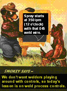
Note. The "medium" size weld droplets in the video shown, are transferring from an 0.045 (1.2mm) steel weld wire. The size of the weld droplets indicates that the weld transfer is in the transition parameter zone that occurs with argon mixes. This transition zone is found between the globular and spray mode. As the spray weld current is increased, the weld drops in the video that look like pulsed weld droplets will decrease in size and change into a continuous weld stream. Depending on the MIG gas mix used, the spray transition weld current with the 0.045 (1.2 mm) steel wire diameter will be approximately 250 - 255 amps. Wire feed 12 o'clock, (fifth turn, 5 x 70 = 350 inch/min) .
Note: For those who want an optimum pulsed MIG Start Point for any steel weld applications > 3 mm, you would set the 0.045 wire at the spray transition start. This logic applies to any wire size.
If the MIG spray wire feed (weld current) is increased above the short circuit and globular to the spray transition current, the higher magnetic forces that result from the increased weld current will influence the profile of the hot wire tip.
The increased weld current, (increased magnetic field) will pinch the MIG molten wire tip to a fine point resulting in smaller weld droplets that eventulally change to a stream of weld metal with micro droplets.
TRAINING - TRAINING - TRAINING - TRAINING - TRAINING - TRAINING - TRAINING - - - -
Their are two ways to get my MIG and flux cored weld process control - best practice training. You can either order one of my programs, or request CUSTOMIZED training, info follows.
FOR MANAGERS OR ENGINEERS THAT ARE INTERESTED IN "CUSTOMIZED TRAINING" FOR THEIR WELD DECISION MAKERS OR TRAINERS, PLEASE GIVE CONSIDERATION TO THE UNIQUE PROGRAMS THAT I PROVIDE IN ASHEVILLE NORTH CAROLINA .
" HOW TO MANAGE A WELD SHOP & ENSURE MAXIMUM DAILY WELD QUALITY
AND PRODUCTION, ALWAYS AT THE LOWEST WELD COSTS".
Asheville Wikipedia Photo by Ken Thomas Rainy.
Blue Ridge, Asheville, North Carolina. Voted # 1 many times..
MY CUSTOMIZED TRAINING:
The following customized MIG & flux cored, Weld Process Control & Best Weld Practice training program is suited for managers, engineers, supervisors, technicians and trainers. The training is provided in Asheville. NC.
In the competitive global weld - fab industry, increased profits will be achieved by those companies that employ, managers, supervisors, technicians and trainers that do not rely on weld sales advice, and have the Weld Process Controls and Best Weld Practice capability for weld process optimization.
Weld Process controls - Best Weld Practices is essential to consistently attain the required MIG - flux cored weld quality with the highest weld productivity always at the lowest possible weld costs.
PROCESS TRAINING & WELD COST REDUCTION OPPORTUNITIES:
Extensive weld cost savings will be found in any weld department in which manual weld personnel and robot technicians no longer have to play around with their MIG and flux cored weld controls.
Extensive weld cost savings are generated in weld departments when weld processes, weld consumables, weld transfer modes, weld deposition potential and weld costs are understood by the weld decision makers.
Extensive weld cost savings will be generated when the manual / robot weld quality is consistently optimized, weld rejects and rework are reduced, and the prevention of weld defects is understood.
Extensive MIG weld equipment and consumables cost reductions are enabled in weld departments in which the weld decision makers no longer rely on weld sales reps for weld advice. These cost benefits will be many;
[] The weld decision maker will have the reasons and proof that your company does not need to purchase costly pulsed MIG equipment that's typically loaded with useless electronic bells and whistles.
[] The weld decision maker will no longer need to purchase three part gas mixes or a variety of different gas mixes.
[] The weld decision maker will not require the costly metal cored wires and will think twice about the flux cored wires purchased.
[] The weld decision maker will dramatically reduce weld fumes and weld grinding enabling a cleaner safer environment and also reduce the requirements for grinding wheels & discs.
A COMPANY DOES NOT NEED A WELD TEAM TO MAKE WELD DECISIONS, WHEN ALL THE WELD DECISION MAKERS ARE "QUALIFIED" TO MAKE CORRECT WELD PROCESS DECISIONS.
My customized course last two days. The course location is in Asheville, North Carolina. With this program I provide what no training company or global educational facility provides. The participants become manual or robot weld process controls experts.
For more info. E Craig. 828 337 2695. E-Mail ecraig@weldreality.com.
PROCESS CONTROL - BEST PRACTICE TRAINING AUTO - TRUCK INDUSTRY:
E-Mail. Ed I wanted to send update about that E-Town, DANA plant
that you visited a few years ago. As you know on your first visit, our robot MIG welding lines were producing less than 40 Ford F-150 truck frames per-hour, and over 90% of the frames required extensive weld rework.
Thanks to your Robot Weld Process Controls - Best Practices Training program, and your process and consumable recommendations, the robot weld results from our employees are today staggering. Yesterday this plant hit very close to a record of 76 frames per hour. We daily attain our average goal of one frame per-minute. We had two recent weld audits. One weld audit had a total of two failures, and the 2nd weld audit was the first 100% pass weld audit in the history of the Ford F-150 line. We have now implemented your robot weld process recommendations in five of our USA plants.Many thanks! Ryan Good.
A grateful engineer, and a grateful DANA Corporation.
Note The DANA corporation is a tier one supplier and a world leader in the supply of drive line products such as frames, axles, drive shafts, and transmissions for light- and heavy-duty vehicles. DANA employs approximately 22,500 people in 26 countries and in 2010 had sales of $6.1 billion.
WELD PROCESS CONTROL TRAINING FOR ANY WELD SHOP USING MIG - FCAW.
E-Mail. Dear Craig, I want to let you know that by using your MIG - FCA weld process control - best practice methods in one of our plants, we have now dramatically improved our weld quality - productivity and reduced our labor - filler metal costs by approx. 45%. We intend to utilize your training program in all our plants.
Lawrence Bower CWI/CWE.
Chief Welding Engineer.
NCI Group. Houston TX.
E Craig's MIG Weld Process Controls & Best Practice Test.
How much do you know about MIG - FCAW Process Controls - Best Weld Practice. The bottom line is Universities, Colleges & Training Facilities, don't provide the weld industry with the process resources they need.
E Craig's Flux Cored Weld Process Control & Best Weld Practice Test.
Robots and downtime in the auto - truck Industry.
The daily Globular MIG Weld Scourge:
MANY WELD AND ROBOT ISSUES ARE CAUSED IN THE AUTOMOTIVE INDUSTRY FROM THE USE OF OVER SIZE MIG WIRES. WHEN THE WELD WIRE SELECTED IS TOO LARGE, THE SPRAY TRANSITION CURRENT REQUIRED WILL TYPICALLY BE TOO MUCH HEAT FOR THE PART THICKNESS WHICH FORCES THE WELD PERSONNEL TO USE LOWER, ERRATIC GLOBULAR TRANSFE WELD SETTINGS.
WHILE MOST WELD PROBLEMS IN ROBOT CELLS ARE CAUSED BY PROGRAMMERS AND UNQUALIFIED MAINTENACE PERSONNEL SETTING POOR WELD PARAMETERS, GLOBULAR TRANSFER IS A COMMON ISSUE WHICH INFLUENCES THE WELD QUALITY, WELD CLEANING AND ROBOT DOWN TIMEWhen the weld management (management maybe not the best word) selected an oversize 0.052 (1.4 mm) MIG wire for the Ford F150 frames, what the unqualified management and egineers were not aware, was that the minimum spray weld current required for the 0.052 wire was too hot for the gage frame parts. Also the pulsed MIG parameters from the 0.052 wires and the costly Lincoln Power Wave MIG power source were inconsistent. As the Lincoln Power Wave pulsed parameters created many weld issues with the large wire, the robot personnel put the data in the regular CV mode and the weld parameters selected, resulted in globular transfer. On parts > 3 mm, globular transfer can produce cold welds with lack of weld fusion and extensive weld spatter.
Combine the common apathetic weld management practice of selecting over size weld wires, with the common lack of weld best practices and process control expertise on the shop floors and you are sure to have extensive robot and weld issues.
Globular MIG transfer produces medium to large weld droplets that cascade across the open arc in an erratic transfer. The high energy globular weld droplets will explode when in contact with both the weld wire and work and these drops will result in excessive, difficult to remove (the drops sometimes weld themselves to the parts) weld spatter.
Globular transfer is a prime cause of robot down time as the explosive weld droplets often attach themselves to the contact tip often restricting the weld wire as it exits the contact tip bore.
As the large globular drops lack the weld energy and plasma velocity of the conventional spray transfer, globular weld transfer not only produces excess weld spatter, it's also a prime reason for lack of weld fusion. There are six primary causes of globular transfer and I cover this extensively in my Manual MIG and Robot Weld Process Control - Best Practice Training programs
My grandson is the one on the right.
E-Mail .from KD - P&F.
Ed, how are you doing? You would be interested to know that by the end of the year I will have close to 100 robots welding with 0.035 (1 mm) wire using spray transfer with no pulsing. It only took 10 years Ed, but we are finally using the recommendations you made in the 1990s. I now have the top Honda guy in North America convinced that instead of using pulsed MIG, the traditional spray mode is the way to go with many of our MIG applications. In regards to your MIG process control training, we now have two plants that are interested in using your process control training resources.
Note from Ed: This E-mail was from a USA, Mid West tier one company that produces parts for Honda and Toyota. Their plant has over 200 hundred robots and Panasonic pulsed MIG equipment. The Panasonic weld equipment and pulsed process was a mandatory requirement of the Japanese parent company. For more than a decade, the Panasonic pulsed MIG equipment generated hundreds of pulsed MIG weld issues that dramatically impacted the daily robot weld quality and production. With all the problems, the engineers in Japan were reluctant to hear that the traditional, more durable, lower cost, North American CV equipment would provide solutions to the majority of their welding issues. I guess even Japanese engineers with time, (ten years) will eventually figure out the solution to simple welding problems.
The inability to establish Best Weld Practices and the general lack of manufacturing weld process control expertise from global manufacturing managers, engineers and robot technicians is completely unacceptable when low cost, highly effective robot / manual weld process control training resources are available. Click for Ed's CD, eight hour, Process Control Training resources.
E-mail from TD. 07 / 2003.Spray - Robots & MIG Wire Burn Backs.
Ed, I work at Monroe, one of the largest producers in North America of auto / truck shocks. Our robots weld on average 200 to 400 parts per-shift. Most of the welds on the gage parts use spray transfer. We average 2 to 6 MIG wire burn backs per robot, each shift.
The burn backs requires that we replace the MIG gun contact tips. The robot down time required to rectify the problem typically means we loose 5 - 10 minutes per burn back. You can imagine over a year the weld production consequences. Ed, what is the primary cause of this common robot problem? Also why does this not happen as frequently with manual welders?The common reasons for carbon or stainless steel MIG Wire Burn-Backs to the Contact Tip:
- Wire burn backs due to the use of oversized MIG wires in which the weld current cannot be used in the spray mode, so the welds are made in the "globular mode". The excessive weld spatter globs block the contact tip orifice and restrict the wire.
- Wire burn backs caused by the use of globular weld data at the robot weld start or weld end data.
- Wire burn backs caused at the robot " weld starts". At a weld start the wire may not have enough forward feed momentum caused by any number of causes.
- Wire burn backs " during the weld". One common cause of burn-back during a weld is when the MIG wire is restricted in the liner, or the tip or from lack of sufficient wire tension from the drive rolls. Restricted gun liners or a robot axis issues in which the gun cable is twisted are a frequent robot causes for wire restriction. These problems frequently result in a wire burn back which can melt the end of the contact tip. These problems can occur at the arc start or during the a weld.
Robot influence on burn backs. When welding with a robot especially when using an 0.035 (1mm) wire, sometimes the robot arm over twists the gun cable restricting the wire. This is noted more with the small wire diameters and specifically when the burn back consistently occurs at a single weld location.
Factors that can influence both wire burn backs and arc starts.
- Wire stick out almost touches the part at the start. At the start the wire short circuits and before the wire can run into the weld it burns back to the tip. Adjust the burn back control in the weld program.
- Poor arc start weld data in the robot weld program. Programmers will benefit from the data found in my Robot Process Control Program.
- Lack or insufficient shielding gas at the weld starts. Shielding gas helps electron flow through ionization.
- Wire feed restrictions or poor wire feed tension.
- Parameters set in the globular mode, leave a ball of weld on wire tip which if oxidized through poor post flow gas coverage will prevent arc starts.


|
More info on the Wire Stick Out (ESO) influence on burn-backs.
When the robot weld starts, the robot control sends a signal to the power source to open the contactor to provide current to energize the weld wire. When the wire makes contact with the work, the wire feed should be feeding forward with full inertia. The current arrives at the wire tip before the wire feed has it's full inertia and momentum and torque from the feeder. The high start current available during the wires contact with the work causes a short circuit that can melt the MIG weld wire back to the tip.
The MIG wire stick out at a weld completion is controlled by the "wire burn-back control data". The wire stick out at the weld completion should always be kept as short as possible. The wire burn back should be set so the wire stick out is approx. 3 - 6mm from the end of the nozzle. A normal nozzle to work distance should 1/2 to 3/4 (12 - 18 mm) depending on the welding circumstances. With these settings you allow a gap between the wire tip and work.Remember. At the robot weld start, there should be sufficient wire to work distance of 4 - 6 mm to ensure the wire is feeding forward before the wire makes contact with the work.
Contact Tip Stick - Outs.
For almost twenty years, the standard robot MIG gun produced in North America and Europe had the contact tips located either flush with the gun nozzle or sticking outside the nozzle by approx. 3mm. The lack of understanding of the influence of Wire Stick Out (WSO) and resulting poor contact tip placements were simply a result of the robot weld process ignorance by the gun manufactures and the robot integrators. Both of these contact tip positions caused numerous robot down time and productivity issues with the world's most common MIG weld transfer modes, spray and pulsed.
If MIG equipment manufactures show little understanding of the MIG process, It should be no surprise that the MIG gun manufactures and the robot integrators who delivered their robot guns with the contact tips sticking outside the gun nozzles simply did not know better. Also someone needs to ask why for decades, did the MIG gun manufacturers classify their MIG guns for use with straight CO2, when less than one percent of the MIG welds were carried out with straight CO2.
At most of the plants I visited that were using spray transfer on parts > 3 mm, the robot MIG guns would be welding with the contact tip stuck outside the nozzle and numerous contact tip issues would be occurring. I would tell the people on the floor to take a hack saw and cut 3 to 6 mm off the contact tips.It should not have taken a rocket scientist to figure out that if you stick a contact tip too close to that spray weld, with the high weld parameters, the high weld heat and spatter will increase the potential for contact tip issues.
As for that pulsed MIG weld, if the contact tip extends outside that nozzle that typically means less wire to work distance is available to create that stupid little weld drop. A drop that needs a greater arc gap than spray, so the pulsed droplets can transfer uninterupted across the arc gap without being in contact with both the wire tip and work.
Many factors influence arc start with robots. All MIG robot programmers should be aware of the factors that effect arc starts, and be aware of optimum start welding parameters of each available mode of transfer and for each wire diameter used. All the data you need is in my books and training resources.How many companies are aware that pulsed MIG welding is much more prone to wire burn back then traditional MIG weld spray transfer?.
The primary reason there is a contact tip concern with many pulsed weld power sources and robots, is with the pulsed process there are electronic time factors and weld wire arc length requirements necessary to create and transfer a pulsed weld droplet, a weld drop that typically provides no carbon steel weld benefits.
For a spatter free pulsed weld transfer, the pulsed weld droplet has to cascade across an arc gap into the weld without contacting the wire tip and weld at the same time.
If a pulsed weld drop makes contact with the work and wire at the same time an explosive short circuit in the pulsed weld drop will occur. The pulsed drop short circuit explosion will cause spatter and possibly disrupt the controlled formation of the next weld drop. These issues (which can typically be heard in the arc sound) can effect the weld and fusion consistency. This situation gets worse as the wire feed rates increase.
The pulsed MIG mode requires a longer arc gap than that is necessary for spray transfer, two to three times the length. The longer arc gap means a shorter wire stick out from the end of the contact tip. The shorter wire stick out increases the potential for wire burn backs. Want a 100 pages of why pulsed can cause weld issues you won't get this data from Lincoln, Miller or ESAB, you will get it from my 600 page "Managers and Engineers Guide to MIG book"
A common automotive plant oproblem. Plants which allow robot welds with oversize contact tips, or contact tips that have excessive tip bore diameter wear. This results in erratic current transfer from tip to the MIG wire?
When you understand WSO you can often increase your robot weld speeds in the range of 50 to 100%.
My Management Engineers book has over 600 pages on how to consistently control both manual - robot weld quality. This book also shows you how to increase traditional MIG robot weld deposition rates (faster weld speeds) in the range of 50 to 100% If you want best practices - process controls for MIG and flux cored welds, this is it. ."Management Engineers Guide To MIG"
The weld speed rates for fillet welds are obviously first determined by the weld size which influences the required weld deposition rate. Another restriction is the weld fusion requirements. Travel too fast with that robot and irrespective of the weld current or weld mode utilized you will have a weld fusion issue. The weld surface condition, the weld length and the shape of the steel (round components are more sensitive to lack of fusion than plate), will also influence the weld speed and weld fusion.
|
Poor welds on frames and axles and we should also have concerns for the shock welds:
Many years ago a major USA shock manufacturer called Monroe, requested my assistance as they could not get their robot MIG spray welds on their shock bracket welds to qualify for a Chrysler "shock load test spec"
The Chrysler engineers required the bracket welds on the shocks absorb at least a 13,000 lb test load. After robot welding the steel brackets with 5 mm fillet welds on the shocks that were only 2 to 3mm thick, Monroe found that their shocks bracket welds would fail prematurely, typically in the 7000 to 9000 lb range.
While the Chrysler weld specification for the shock bracket welds required that the welded brackets pass a test load of 13,000 lbs, it took me less than two days of welding and testing on the shock bracket welds to reveal that any test load of less than 19,000 lbs, indicated lack of weld fusion in one of the four bracket welds.
There were three reasons that the shocks could not meet the minimum shock weld test load requirements,
[1] the robot spray transfer welds were made on "cold rolled round parts",
[2] the robot weld speeds for the small weld lengths were "set too high",
[3] the robot weld lengths on the brackets "were to small".
After I figured out the weld problems, I changed the weld wire size to a smaller wire which increased the weld current density. I reset the spray parameters, extended the shock bracket weld length by another 3 mm. After my changes, the shocks bracket welds failed at an average load test of 21,000 lbs.
How fast, how slow should the robot go?
If all MIG welds were evaluated for the internal weld fusion, there would be more focus on the weld speeds utilized. Many robots today are either welding too fast or too slow. A common problem is that the MIG wire size may be wrong, or maybe it's because pulsed, globular or short circuit is being utilized when spray would be superior. Maybe the weld issue is the part design, joint type, part thickness or ridiculous gaps many auto / truck companies present to the robot weld cell. Optimum weld speeds for all applications and weld compensation data for potential weld issues are covered in my books.
Many companies who purchased pulsed MIG equipment for their robot cells, may have had high robot weld speeds and high weld production expectations. The majority of weld decision makers who purchased the MIG equipment for the robot cells were under the impression that with the new, sophisticated, pulsed MIG equipment, that their Multi - Wave Form, Pulse on Pulse, AC - DC, Fuzzy Weezzy, Remote Wireless Controlled, $13000 MIG power source, that they can now 'weld faster" with more production that that possible with a conventional MIG power source on applications > 3 mm.
The MIG robot weld speed reality is this. The low cost MIG equipment that has delivered MIG spray transfer since the 1950s has always provided the fastest most stable MIG weld speed potential on carbon, low alloy and stainless steels parts > 3 mm. Note in Australia using my MIG process control resources, companies are making spray welds in the 15 - 25 lb/hr range. Few weld shops in North America, when using MIG have attained over 16 lb/hr.When welding carbon and stainless steels under 1/8 (3 mm), if you have the right pulsed MIG equipment, pulsed MIG can provide higher weld speeds than short circuit welds. Conventional spray is typically too hot for these applications.
The following are a few MIG Spray Transfer weld facts:
For those of you that believe the pulsed equipment is depositing more weld or delivering faster automated weld speeds, on applications > 4 mm, compare what you are achieving with this weld reality.
[1] With low cost, traditional, durable CV MIG equipment, spray transfer when used on parts > 4 mm, weld deposits in the range of 8 - 25 lb/hr are being utilized. On these applications, the pulsed MIG mode can not deposit more weld metal than spray transfer. The typical, stable pulsed spray deposition range is 8 to 14 lbs/hr.
,
[2] Using conventional weld practices, the typical spray transfer "robot or automated, common, 1/4 (6 mm) fillet welds" made on parts > 5 mm, are made at weld travel speeds of 18 to 23 inch/min. On these parts pulsed cannot provide faster weld speeds.
[3] When welding the common 3/16 (5 mm) fillet welds, the typical weld deposition rates with an 0.045 (1.2mm) wire using spray transfer will be 10 to 12 lbs/hr. The automated weld speeds for this weld should be in the 40 to 60 inch/min range. With extended wire stick outs, (information in Ed's "Management Engineers MIG" book) I have produced these 3/16 fillet spray welds at robot weld speeds up to 85 ipm. On these parts, the pulsed process will not provide faster weld speeds, however the pulsed mode can if required provide lower weld heat (lower distortion) than that which results from spray.
One of the very few limited Pulsed MIG weld benefits: The pulsed mode when used and set correctly, on steel applications less than 1/8 (<3 mm), can provide higher weld deposition rates than short circuit or globular transfer. As short circuit is a poor choice, pulsed MIG is also a logical choice for < 3 mm aluminum applications.
When asked for his opinion on Spray transfer versus Pulsed MIG, a chap called Albert might have said the following.
"Constant weld energy attainable from CV spray transfer
is a logical requirement for constant weld fusion".
The three most important aspects of any weld, are the size, the weld fusion and quality attained.
[] With more than 90% of all MIG welds there is no evaluation of the weld fusion attained.
[] Every weld shop that MIG welds should be aware that the primary weld concern with most steel and stainless welds over 3mm is to attain sufficient weld fusion in a consistent manner.
[] In contrast, a primary MIG concern with most steels under 2 mm is avoid weld burn through and distortion.
PULSED MIG AND HOT CRACKS: A common concern you will find with high deposition rate pulsed welds. When pulsed is used in the high, "stable spray transfer wire feed range", the pulsed MIG arc is influenced by the high pulsed Hz and high peak current required. This combination often provides a highly agitated pulsed arc that results in a narrow, high velocity plasma. This high velocity pulsed plasma can provide a digging effect resulting in crater problems and narrow weld penetration profiles that can lead to hot, center weld cracking.
Ed made the following manual spray transfer weld with a $250 traditional MIG CV power source using an 0.045 (1.2 mm) E70S-3 MIG wire, set at 450 ipm. (1 - 2 o'clock), approx. 12.5 lb/hr. These deposition rates are extended with increased WSO.
What's that $6000 - $12000 Pulsed MIG power source going to achieve?
The spray transfer arc plasma not only conducts the weld current, the plasma with argon mixes also shrouds the electrode wire tip. In contrast, when using straight CO2, the arc plasma occurs "under the weld droplet being formed. This plasma supports the weld drop as it forms and grows till eventually it drops off the wire tip in an erratic manner. The CO2 plasma is the reason you cannot get spray transfer from straight CO2. It's also the reason the CO2 content is limited to approx. 20% in argon mixes. See MIG gas mixes if you want to cut through gas salesmanship and read more practical gas data.
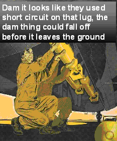
When a plant MIG welds bombs for the Airforce, you would think some manager, engineer or supervisor at this defence contractor's plant, would know the difference between a MIG short circuit and a MIG Spray transfer weld.
In manufacturing, the real weapons of mass destruction is often a result the management process apathy thats found in the engineering department that make products.
Many years ago, a well known US military defence contractor wanted to me to optimize the bomb lug welds that attached the cylinder shaped bombs to the underside of the fighter planes. My weld focus was to improve the MIG weld fusion that was being attained between the thick bomb lugs and the heavy wall (1/2 - 1 inch ) bomb casings. The MIG weld process improvement were really necessary as when I checked, the majority of the bomb lug welds being daily produced at this plant, revealed that the majority of the lug welds had more than 50% lack of fusion.
The first thing I found at the bomb plant, was their was no qualified weld management or supervison, just a bunch of military type engineers and white shirt managers that thought they were managing a parade ground. The welders who did not know better were utilizing poor MIG weld practices and using both the MIG short circuit and globular weld transfer modes. Using these two low energy MIG weld transfer modes that were more suited to 14 gage welds than the 1/2 to 1 inch parts welded, it was simply impossible to get the weld fusion desired for the lugs. To rectify this companies weld issues, I had a choice between the use of pulsed MIG or spray, (they had recently purchased new pulsed MIG equipment). After I produced the pulsed and spray welds at the same wire feed rates to maintain production. For both processes I set optimum weld parameters. The weld macro weld tests clearly indicated that the spray transfer mode had to be the first choice to provide the consistent weld fusion necessary. By the way I knew this would be the result before i welded. I simply did the two weld mode tests to show the engineers that the solution to their weld problems was always with the old equipment thay had and they did not need to take the sales reps advice and purchase the pulsed MIG equipment. After the weld tests were done I provided training for both the workers and managers and that was that.
Power point from my Robot MIG Process Controls Training Program
The argon mix plasma that envelops the MIG wire tip, allows the weld droplets (transition) or stream to transfer axially, in a stable manner. If more than 20% CO2 is utilized the plasma is lowered under the droplets, supporting the drops till they grow and erratically transfer when they succumb to gravity
Note: In this video shot the spray transfer is in the transition zone found between short circuit and spray. This zone results is a distinct controlled weld drop that looks very like a pulsed weld. The spray plasma also enables stable transfer of the electrons as they transfer from the negative work, weld cathode spot locations, to the positive anode areas located on the electrode wire tip.
While the negative electrons are driven upwards to the positive wire tip by the weld voltage, the positive larger gas molecules are driven downwards to the negative work. The electrons on there way to the wire tip collide with the larger mass, gas molecules. The electron and gas molecule collision causes the gas molecules to split (ionization) adding more free electrons and protons in the arc plasma, this increases the plasma ionization energy. The electron and gas molecule collision increase the MIG plasma arc conductivity and the energy.
The mill scale on that hot rolled plate surface to be MIG welded may be a poor electrical conductor causing electron reduction and arc instability. The electron conductivity of spray transfer is influenced by both the mill scale thickness and mill scale composition.
Mill scale acts as an insulator which can impede the electron flow from the cathode spots on the weld surface as they travel to melt the MIG wire tip. As mill scale increases the weld energy is reduced and to sustain the open arc, the MIG weld voltage has to be increased. Mill scale melts at a higher temperature than the base metal and typically the welds become more sluggish.
If you make a spray transfer weld on carbon steel without mill scale, and then without changing the weld voltage, make a spray weld on a part with mill scale, the welder would note the arc distance from the wire tip to the weld has reduced. The arc length reduction is a result of a decrease in electron conductivity, less electrons = less energy to melt tip of MIG wire and the wire gets closer to the weld. The shorter arc length often results in the MIG wire running into the weld, displacing the weld causing weld spatter. To reduce the weld spatter would require that the welder increase the weld voltage to increase the arc length. As we don't teach welders this simple fundamental fact we end up each day spending millions removing excess weld spatter.Even with the correct voltage, the higher melting temperature mill scale can affect the weld fusion - porosity potential and frequently these welds will solidify in a convex shape with a roll over at a fillet weld toe. The influence of mill scale and the process requirements to compensate for the sluggish welds and spatter control, is another reason why weld personnel would benefit from my weld process control training resources.
The influence of the MIG arc on the steel mill scale.
An intense, consistent high energy arc as found with a spray transfer weld is more beneficial than pulsed MIG with it's fluctuating peak to back ground current when dealing with mill scale issues.
In contrast to pulsed MIG, the CV spray arc will;
[a] assist in maintaining consistent electron flow adding to arc stability,
[b] assist in the removal of surface contaminates,
[c] provide superior wetting for a sluggish weld,
[d] provide consistent weld fusion.
[e] provide less weld porosity
With pulsed MIG, the plasma is influenced by the peak to low background current variations and the weld current and voltage fluctuations which are common from the electronic pulsed MIG equipment. Also pulsed MIG often utilizes low energy gas mixes like argon oxygen or argon 5 - 10% CO2 which also decrease the weld energy.Weld Voltage and Weld Current Stability?
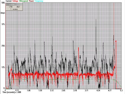
2004: While testing Japanese and Americam pulsed MIG equipment, we had this oscilloscope graph made of a carbon steel "pulsed MIG weld" set at optimum weld parameters. As the graph below indicates, when using one of the most costly, popular and sophisticated pulsed MIG power sources sold in the USA, that weld current and voltage instability is the norm.
Above pulsed MIG voltage and current, note difference below..
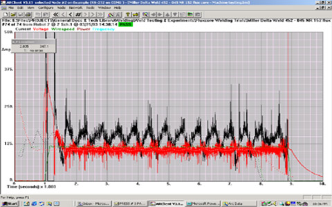
In contrast below, this graph is regular spray transfer taken at the same time from
a CV MIG power source that cost 1/3 the price of the pulsed power source.
Steels or Aluminum, Spray always more Stable.
In contrast to spray, the pulsed process typically provides a narrower plasma that fluctuates with the changes from peak to back ground current. As you increase the pulsed welding parameters to traditional high spray transfer wire feed levels, when welding steels > 5mm, the pulsed plasma zone which is influenced by the "high frequency, high peak pulsed weld current" can become intense. Typically the excess high peak current can result in an intense pulsed plasma that's conical and narrow in shape. The resulting narrow intense plasma configuration can cause an arc digging effect that may result in deep narrow weld penetration. These pulsed MIG welds may produce,
[a] narrow weld beads that depending on the application can produce (hot center weld cracks),
[b] excess undercut,
[c] frequent crater cracks.
The shorter arc length (wire tip to weld surface distance) allowed by spray transfer can provide a highly localized, intense plasma configuration that is very beneficial for the weld stream transfer on robot high speed steel welds, and also beneficial on high deposition welds, large size welds or when welding plate with surface contaminates such as mill scale.
< 2005: How many of you have used pulsed MIG for high speed welds >30 ipm, and found the weld transfer was inconsistent and the welds were skipped. Just about every auto - truck wheel or torque converter manufacturer found this problem with their costly pulsed MIG equipment, yet these manufactures continued to utilize and purchase the pulsed weld equipment that caused the issues.
The Pulsed MIG mode requires a longer arc length: For the uninterrupted formation and transfer of a pulsed weld drops across the open arc, the pulsed MIG mode requires a longer arc length than traditional spray transfer. The bottom line, depending on the weld surfaces the weld settings and pulsed equipment utilized, the pulsed mode on many welds can be arc length (voltage) sensitive. This sensitivity upsets the pulsed weld droplet transfer causing arc instability (often evident in the arc sound produced). In contrast, the traditional spray mode in which the metal transfers in a stream can utilize much shorter arc lengths and the continuous weld stream is hardly affected by minor arc length variations. The arc length sensitivity is an important point as it affects;
[a] Shorter, less sensitive arc lengths allowable with spray transfer improve arc stability when welding at a high speeds.
[b] Shorter less sensitive arc lengths allows longer wire stick outs which reduces wire burn backs to the contact tip.
[c] Shorter less sensitive arc lengths are beneficial when welding on mill scale or coated metals.
When spray transfer welding on troublesome mill scale applications, a high energy MIG gas mix such as argon with 15 to 20% CO2 is recommended. The 15 to 20% CO2 gas mix in contrast to a lower CO2 mix, or argon oxygen mix, enables higher weld voltage to be used and promotes higher energy at the cathode locations on the plate or weld surface.
Note While at AGA, Ed and his friend John Lowery, were the team that introduced the gas mix argon - 20% CO2 to the USA. In the following years many of the weld distributors who were making this gas mix were putting too much CO2 in the cylinders. With this in mind Ed lowered the CO2 content and then introduced to the North America the argon - 15% CO2 gas mix.
What makes CO2 gas unique? The CO2 plasma provides unique "gas dissociation properties". In the MIG arc. The CO2 molecules break down from CO2 to CO and O2. When these molecules get close to the cooler weld surface the CO - O2 molecules form back to CO2. This gas dissociation, "molecular change" adds energy to the weld.
In contrast to argon with 5 - 10% CO2, and tri mixes containing argon - CO2 - oxygen, the 15 - 20% CO2 typically requires 1 to 2 extra weld volts to sustain the arc. The extra voltage and CO2 arc dissociation properties improves the electron flow, improves the arc stability and enables additional weld energy for improved weld fusion and lower porosity.
For those companies that use argon oxygen mixes, or the heavily marketed, useless three part mixes containing argon - CO2 - oxygen on carbon steel applications that have mill scale, (applications >3/16), they should realize they are jeopardizing the weld fusion potential and increasing weld porosity potential.
The oxygen and low CO2 in many argon tri-mixes, results in a spray transfer plasma in which low to medium weld energy is generated in the outer periphery of the plasma. This results in finger or nipple shape weld profile. As the narrow finger weld solidifies rapidly this increases the opportunity for weld porosity to form especially in the finger shaped weld root. It's very common for this defect to show up in ultrasonic evaluation or with x-rays on fillet welds on parts > 5mm.
[a] weld porosity,
[b] welds with lower weld energy, resulting in inferior weld fusion profiles,
[c] less gas in the cylinders than that attained with argon 15 - 20% CO2 mixes.
For extensive weld gas data see my weld gas section, or better still, invest a few dollars on yourself and purchase one of my welding books. My " Management Engineers Guide to MIG" has over 600 pages on how to control all MIG and flux cored welds.
Note Ed was a key writer of the USA AWS "MIG Gas Specifications".
E Mail. July 05.
Ed. It looks like we are just starting out on a new Chrysler project welding a galvannealed product. Galvanneal NS 6000 D series 44a. According to the Chrysler weld specification, with MIG we would be allowed to use a solid carbon steel ER 70S-3 MIG wire, however they require a 75 argon / 25 CO2 gas mixture for this application. I think Chrysler takes the cake on this MIG gas selection. By the way if our engineers had selected galvanized material, according to the Chrysler spec we would have been forced into using the terrible Lincoln self shielded FCAW process.....Is the Chrysler weld engineer from this planet? What I also don't understand is the fact that they are specifying a coated material, and then we are still required to e-coat the part. I wonder what the reasoning is behind double coating the cradles.....I'm sure they don't even know.
Regards GR. Tier One Supplier.
Want to know how to reduce "cracks" or Arc Blow.
Minimum Spray Transfer weld current with argon > 10% CO2 Mixes.There is an optimum MIG Wire Diameter for every application thickness.
As I have mentioned at least 600 times, the auto / truck industry is one industry that for decades has been notorious in it's selection of unsuited MIG and flux cored electrode diameters for welding steel applications < 6mm.
Few companies understand the weld wire, weld mode, weld current, weld size, weld travel rate and part thickness relationships. For those individuals that want to proffesionally manage the MIG and FCA weld processes, this is an extensive part of my books and weld process control training programs.
2013: Did you ever consider why, after at least four to five decades of making MIG welding equipment and welding consumables, that Lincoln, ESAB, (Linde), Miller or Hobart did not put practical MIG weld parameter information on their MIG wire packages or along side the relevant MIG wire feed or power source parameter controls?
I believe the reasons the MIG welding electrode wire manufacturers never provided their weld customers with practical, cost effective MIG or flux cored welding data on the wire boxes, is because they did not employ management or engineers that had figured out the simple relationships that exist between the few required wire feed and voltage settings necessary for the majority of all the common global MIG and flux cored applications. To overcome their focus on weld process controls I developed the "Weld Clock Method".
In the weld equipment and consumable distributor industry, sales and real world data were often far apart. The incredible lack of MIG and FCA weld process expertise that prevailed from the world's largest weld consumable manufacturers and thousands of distributors is not that unusual. As we all are aware just because you make something does not necessarily mean you are an expert in it's use. The sad issue today for the self taught global weld industry, after 50 years of weld misinformation, too many weld shop still rely on these same companies for weld advice.
Note: In the 1980s in a marketing program I set up at AGA in Cleveland. I introduced MIG weld wires which were enclosed in boxes in which I had printed all the short circuit and spray weld settings required for any applications with the 0.035 and 0.045 wires. With Airgas and Liquid Carbonic, I created simple two part SteelMiX and StainMix gas mixes, and then I put the labels on the cylinders that again provided all the possible optimum MIG settings.
Note: Ed got the GM management - engineers to stop using the nasty self shielded flux cored weld wires for the CORVETTE body welds, and then trained the GM workers on how to use the MIG process on the same application. Keep in mind, this was after MIG had been available for four decades. This shows that in the automotive industry, you can always hope that sanity will prevail. By the way, I would like to thank the Corvette racing team for making me there unpaid MIG weld consultant..
For an experience you may not enjoy. Next time you visit a Fabtech or AWS weld show, ask the Lincoln - Miller - ESAB - Panasonic rep the following technical question. Look for someone demonstrating pulsed MIG, then ask them to do a 6 mm vertical up, carbon steel or stainless fillet weld on > 1/4 (6mm) plate. After the weld, look the rep in the eye and ask how his pulsed wire feed rate compares weld deposition wise with an 0.045 (1.2 mm) E71T-1 wire set at a feed rate of 400 in./min. The weld you view and the answers you receive to this fundamental simple weld question will show you how little or how much is known by the so called weld equipment or consumable experts.
The sales reps promoting pulsed weld equipment at the AWS or Fabtech trade shows may extol the virtues of their weld equipment benefits, however, the bottom line is those benefits may dwindle quickly when you take a real look at the inconsistent arc characteristics and then provide a realistic comparison of their process or equipment against other processes, mode of weld transfers, equipment and consumables.
Before weld personnel provide an opinion on a welding process or weld consumable, they should have all the facts on the processes and consumables that compete with their process or consumables. And of course if they were a true professional they would then provide an answer without product or process bias.
The Harley management did not know the meaning of process ownership.
When Ed established the robot welds for Harley bike frames, he resisted the use of the pulsed mode (at that time arc instability issues with the pulsed equip.) and turned to low spray transfer. Ed set 3 simple weld schedules for the more than 50 welds required on the frames.
Note on Harley lack of management: At the main Harley Bike plant, I sat in on a meeting in which two weld engineers and nine robot personnel discussed for more than two hours a robot MIG weld spatter problem on a bike gas tank. At the end of two hours, the problem was unresolved. Thanks to the Harley "hands off" management approach, I was not allowed to speak at this meeting. The management were afraid I would upset the Harley sensitive workers. For me, that meeting was a sad engineering situation. This American company with it's global brand reputaion indicated that it's combined mangement and engineering resources could not resolve a simple weld voltage issue that should have taken two minutes to resolve.How many global production man hours are lost daily with inexperienced weld team meetings having discussions on robot weld issues which with a little weld process expertise would take a few minutes to resolve? Ed Craig. 1985.
If you want a quick evaluation of the weld process expertise in your shop, ask three of your welders or the weld shop supervisor to tell you the 0.045 (1.2mm) wire feed position in which the start point occurs for spray transfer. You may be surprised at the diverse incorrect answers provided for the world's most popular wire size and the world's most utilized weld transfer mode.
If you think your weld personnel fully understand the weld process they make a living from, why not give them my MIG weld process control quiz?
"Play Around". No managers or engineers should allow these two words to be used for any manufacturing process that is critical for an organization.The good news is the common lack of MIG and flux cored weld process expertise can be quickly eradicated in any weld shop. First managers have to put their focus on the root causes of their weld issues and always remember that quality - productivity responsibility and product liability starts in the front office, not on the factory floor.
HANDS OFF WELD MANAGERS AND ENGINEERS WON'T MIND WHEN THE PURCHASING MANAGER MAKES WELD PROCESS - CONSIMABLE DECISIONS.
When purchasing personnel make weld consumable or equipment decisions, the management supervisors & engineers should resign.
Throughout the weld manufacturing industry and especially common in the auto - truck industry, "purchasing managers" and other inexperienced personnel are frequently involved in weld consumable and weld equipment selection decisions.
Perhaps your company has a purchasing manager that found out that "bigger weld wires cost less than smaller wires and therefore recommended the large wires which resulted in a "weld wire cost savings".
When selecting the correct MIG wire diameter, the optimum weld current compatibility of that wire with the part thickness, the weld transfer mode and weld size are the prime considerations for consumable selection. Selecting the optimum MIG wire diameter requires MIG weld process expertise. For those companies that are utilizing wire diameters that are too large, most of the welds produced with the over sized weld wires will be in the globular mode the weld productivity, costs and weld repair consequences will be extensive.
It's a fact that more than 75% of the MIG and flux cored robot applications welded in the North American auto and truck plants, are using weld consumable sizes and types that are not optimum for the welding applications.
To Ed Craig. Sept 2004.
E-Mail.Question: Ed. Our company is a US based, Japanese auto parts manufacturer. We use Japanese robots to MIG weld 1 to weld 3mm steel parts. We use the pulsed MIG process, argon gas 10% CO2 mixes, and 0.045 weld wire. We use Japanese MIG wires equivalent to AWS E70S-6. The manager wants to reduce robot-welding costs. I am currently writing a cost justification calling for a change to a MIG wire manufactured in North America -- possibly an 0.035-in. wire. Our company engineers, however, insist on sticking with the imported Japanese MIG wire which costs approximately $0.50 more per pound than the equivalent USA MIG wires. These engineers also inform me I cannot change the wire size or type since the code states this wire is an essential weld variable. Am I correct that according to most codes, as long as both wires are E70S-6s, they are interchangeable and therefore a none essential weld variable?
Ed's Answer:
Essential weld variables are three words that may carry some weight in an organization that welds within the boundaries of codes such as API or ASME. However from a common sense perspective these three words should never be used within the boundaries of an automotive plant and especially in your plant.
First, irrespective of the codes or weld procedures in place, as long as the plant uses argon mixes there will be no negligible influence on steel weld mechanical properties, whether the MIG wire is American or Japanese E70S-3 or E70S-6. Both these MIG wires are qualified for argon mix use. Second, if the company changes the wire size, it's logical to redo the weld procedure.
Importing costly MIG wires into the USA a country that has the world's largest MIG wire manufacturer makes as much sense as exporting USA coal to Newcastle UK. Any US or Japanese auto-manufacturing company that throws money out the window by importing expensive Asian MIG weld wires needs a new plant and engineering manager.
It makes little sense to be concerned about so-called essential weld variables when the pulsed-equipment manufacturers are making radical E –Prom changes to their weld equipment every few months. Each new robot line brought into your plant has pulsed equipment that may have little in common with the pulsed-weld equipment purchased two years ago.
Weld procedures have little meaning when the weld equipment used is either changing or inconsistent and lets face it the majority of robots sold do not have proper calibration between the robots, power sources and wire feeder. It also makes little sense to worry about essential weld variables, when every day some robot technician in your organization is probably making unqualified weld changes to the robot data. And most important, why worry about essential weld variables when the parts you produce will likely suffer from dimensional issues that afftect the weld fit and weld gaps.
It's rare in auto - truck manufacturing plants that strive for manufacturing autonomy to see effective weld practices or effective robot weld process controls implemented. It's even rarer to find engineers in this industry who have in-depth weld process control expertise. This of course leads to the weld consumable cost discussions and distractions from the real weld issues.
To have an impact on a plant's weld costs forget about saving pennies on consumables and start out with an evaluation of the “weld deposition rate potential” and the real-world weld efficiency of the robots. Evaluate the robot's downtime and the robot weld rework generated. Compare these numbers with the information attained in my robot-weld-process-control book. Check out the high weld-speed benefits of a 0.035 or 0.040 in. wire on parts less than 0.080 in.The engineers and managers who want you to use the Japanese weld wire do so because they fear process change. My solution would be to fire all the engineers and managers involved.
For decades the best MIG weld wire for the auto and truck
industry is of course the one they rarely use.
Weld Question: We weld carbon and stainless steel parts 3 to 5 mm. What's the best MIG electrode size for spray transfer robot applications? Our key weld requirements are;
[a] Attain consistent optimum side wall weld fusion.
[b] Attain welds speeds above 40 ipm.Answer: Considering the weld current compatibility with the part thickness and desired weld size, the following is a logical choice of MIG wire size selection.
[a] Robot - Manual Spray welds on steel / stainless parts 3 - 5 mm. If available, the first choice MIG wire diameter would be the 0.040 (1.1mm) MIG electrode wire. If the 0.040 wire is not available, use the 035 (1mm) wire. Wires smaller than 0.045 provide superior small weld puddle control and the spray current range of these wires is better suited than 0.045 wires.E-mail March 2007.
Ryan Good. Dana Corp.
Hey Ed:
Just thought I would drop you a line and let you know that in the beginning of April, thanks to your advice, we will be working on switching over the 5th Dana plant to an 0.040 MIG wire and using the spray transfer mode instead of 0.052 globular mode we were getting with the Rapid Arc (Lincoln's pulse MIG program). Thanks Ryan.
The 0.045 wire also can provide spray transfer at typical current of 250 - 380 amps. For the 0.052 and 0.062 wires to out perform the weld deposition rate of the 045 wires, the larger wires would have to use well over 400 amps, this higher weld current promotes excess weld fluidity and is hard on both the weld equipment and welder's skin.When robot welding in the "flat positions" rather than the horizontal position, and the parts are >5/16 thick, an 0.052 (1.4mm) MIG wire is beneficial and this wire will cost less than the 0.045.
Lets see, the electrode size recommendations should provide an optimum spray transfer current range which is compatible with the part thickness welded and allow control of the weld fluidity and oxidation.
This is an interesting approach to weld wire selection and weld process control. Weld current compatibility with the part thickness means the electrode selected can use the high end of it's optimum operating parameters without concern for an agitated arc plasma and a turbulent weld puddle. Using current compatible with the part thickness means no concern for over heated, oxidized welds or weld burn through. The welding parameters will allow high wire feed rates resulting in optimum weld deposition rates and maximum weld travel rates for the weld consumable utilized.
Weld Current Compatibility with the Part Thickness.
E-Mail from Shawn.
Question: Ed on our robot application we have a multi-process, pulsed MIG - short circuit - spray power source. We weld auto thin gage steel parts from 1 to 4 mm with an 0.035 wire. Is there a defining line when we should switch from one weld transfer mode to another?
Answer:
Shawn this is a great question.
[] For robot applications < 0.070 I would use short circuit before pulsed. The short circuit mode is an arc on / arc off weld transfer and therefore provides less potential for weld burn through, especially if weld gaps are involved.
[] For applications 0.070 to 0.150, pulsed MIG fits the bill and will typically allow the use of higher wire feed rates than short circuit, however if gaps greater than 0.060 occur remember to set the parameters to short circuit. .
Robot welding on parts > 0.150 to 4 mm, take your choice of spray or pulsed. If using spray use an 0.035 wire at the transition point.. If the welds are is too hot consider pulsed and an 0.045.
I hope you are not still taking notes as that proves like me that you don't have a life.
Invest in yourself and consider one of my books or training resources. This book is my robot - manual MIG self teaching process control book. It's available in both English and Spanish. The book has 170 pages with 170 MIG questions all directed at weld process control and weld parameter selection simplification through the easy to leran weld clock method.
For your weld shop training needs you would purchase three items. This self teaching book, a unique CD power point program and a video. These are the most practical weld data resource your weld personnel will ever learn. Welders, robot programmers, robot operators, QA personnel, weld supervisors, managers and engineers, all will benefit from this valuable weld process resource.
It's important that all weld personnel who make weld decisions be of "one weld mind set". Click here for the training info.
,
If you are just entering the weld profession, you will be glad to know that
weld renumeration in 2014 is just about where it was 25 years ago.
MIG Spray Section Two.
[] Robot wire burn backs and arc start problems cause extensive down time. Find the solution.
[] Find out how to deal with galvanized welds.
[] Recognize the different types of weld porosity, and the root causes.
[] Find out why some Lincoln - NS and Hobart MIG wires may be part of your weld problems.
[] Find out why you have stop your welders using STICK weld techniques with the MIG process.
[] Learn both the visual and sound approach to setting optimum MIG welds.
Ed's now Em's Self Teaching - Training materials.