|
Welcome to Robot MIG Weld Issues and Solutions.
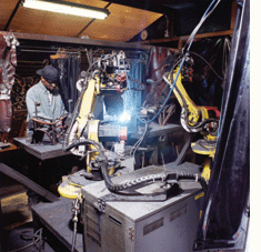
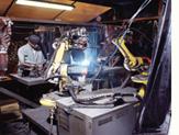
The next time you apply for a job in welding, you may walk into a plant that has robots that are 5 to 25 years old. Those robots will have unique issues and limits that come with the age of the robots. Also in the robot cells will be electronic inverter pulsed MIG units with built in robot interface, or old cells with CV MIG equipment with seperate interface. The robot cells that will provide the most issues, will be those robot cells with the electronic inverter weld power source.
If I asked you to replace your computor with a ten year old computor, we know how that would go. When you have to work with aging, electronic pulsed MIG equipment, you typically will be having weld issues that are a direct result of that MIG equipment. And what many will not be aware is even with new pulsed equipment in 2019, depending on the power source selected, you will still be having robot weld issues that are a direct result of the pulsed MIG equipment. This section and my pulsed MIG section will hopefully make you aware of the many pulsed weld issues that you can anticipate, and some of the logical weld solutions.
ON THE SUBJECT OF POOR PULSED AND INVERTER MIG EQUIPMENT, LETS START OF WITH HOW JAPAN ADDED TO THE ALREADY COMMON POOR ROBOT MIG WELD QUALITY IN THE USA:

THE REALITY WAS FOR DECADES THE JAPANESE WERE NOT FAMILER WITH OPTIMUM QUALITY MIG WELDS AND A PRIME REASON WAS THE GAS MIX THEY UTILIZED.
FOR MANY DECADES, THERE WAS A LACK OF LOW COST ARGON AVAILABLE IN JAPAN, AND FOR MIG WELDING, THIS COUNTRY MOSTLY USED STRAIGHT CO2. IF YOU WANT TO KNOW WHAT AN ERRATIC, GLOBULAR MIG WELD TRANSFER LOOKS LIKE ON WELDS SURROUNDED BY SPATTER, VISIT MY MIG GAS SECTION.
IN GENERAL IN JAPAN AS THE CASE IN THE USA, THERE WAS
EXTENSIVE MIG PROCESS AND MIG GAS MIX IGNORANCE, PROCESS CONFUSION WAS THE NORM AND MIG PROCESS CONTROLS & BEST WELD PRACTICE
EXPERTISE WAS RARE AS AN HONEST POLITICIAN.
SO WHILE THE JAPANESE AUTO COMPANIES SUCH AS TOYOTA, HONDA AND MAZADA BUILT GREAT VEHICLES, IN GENERAL HEIR MFG. MANAGEMENT KNEW LITTLE ABOUT THE REQUIREMENT FOR ROBOT (OR MANUALl) MIG WELD PROCESS OPTIMIZATION. THAT WAS TRUE IN 1980s, AND IT WILL STILL BE TRUE IN 2020.
THE GROWTH OF ROBOTS AND INCREASE IN ROBOT CELL ELECTRONICS:
ONE JAPANESE SOLUTION TO THEIR DAILY POOR MIG QUALITY WAS FOR COMPANIES SUCH AS PANASONIC TO BUILD WHAT THEY THOUGHT WERE SOPHISTICATED ELECTRONIC MIG POWER SOURCES. THEY SHOULD HAVE STUCK TO MAKING TVs. THE ELECTRONIC MIG EQUIPMENT THEY PRODUCED WAS THE WORST MIG POWER SOURCES THAT WERE EVER BUILT:
Note: Japan is a country that after the second world war had
few industrial gas plants. Argon was not that readidly available or considered cost effective for producing MIG welds. In japan as the erratic CO2 MIG weld transfer produced extensive weld spatter, extensive grinding of the MIG welds was considered part of the MIG weld process requirements.
Note: While the Japanese at least had one excuse for the poor MIG weld quality produced, in contrast, the North American Auto industry MIG welds were often not much better and they had acess to low cost argon mixes. In North America the best MIG weld equipment and consumables have always been available, but the reality was the auto / truck managers and engineers responsible for MIG welds knew little about the MIG process control requirements for process ownership. This was true in the 1980s and is true in 2019.
Visit my robot weld management section, for the general pathetic auto - trick robot weld quality & productivity results that have been attained in the last three decades.
So the Japanese decided to build there cars and trucks in N. America and when the Japanese car / truck plants opened their inexperienced Japanese senior mfg. management, requested that their inferior Japanese robots and MIG weld equipment be utilized here.
I love my Avalaon (thank god i cant see the welds) however in the days of robot growth in N.America
the Japanese, 20th Century engineering contribution to our North American Auto. / Truck Industry, was that they introduced their apanese robots, with their confused illogical weld software, with lack of TCP control ability, and poor robot to power source calibration, and with of course, their unstable, innefective Japanese inverter electronic MIG weld equipment. They also bought over MIG weld wires produced in Japan that would have been welll suited for use around a farm.
For decades, around the globe, "playing around" with MIG weld controls is what many
MIG welders and robot technicians have had in common.
My Robot MIG weld Process Controls dramatically reduces robot down time, weld rejects & weld rework, and also enables the highest possible robot weld productivity. My self teaching / training resources are the tool that management requires to teach themselves and to train their employees to attain max. robot MIG weld quality and production.
Note: Ironically I have made these resource available for two decades, (updated annualy), however most plant, engineering and mfg. managers / enginners would not be looking for a process control tool such as this, as they are simply not aware of their, or their companies lack of MIG weld process controls and best weld practice expertise.
It's important for robot weld personnel to keep in mind, that if somone was working with Japanese Robots and Japanese MIG equipment from approx. 1980 to the present, they
were using robots that were typically inferior to the MIG weld robots made in Europe by ABB, and the Japanese MIG weld equipment they were using daily, was very inferior to most of the MIG weld equipment being sold by companies such as Miller, EASB and OTC.
It took over 20 years but around 2012, the Japanese electronic pulsed MIG equipment
that was being developed for argon mixe steel welds made some improvements, however for most steel MIG welds, their pulsed MIG equipment was simply not necessary, and this equipment was still the root cause of many MIG weld issues in robot cells.
2019: Please Note. The Pulsed MIG process is not required for most "manual" steel MIG welds, and for decades this equipment has been the root cause of numerous weld issues. However as we are aware, as the pulsed MIG equipment is loaded with electronics, the pulsed inverter units lend themselves to having a built in interface that can communicate readily with the robots. Most of these pulsed MIG units will also offer apart from the pulsed mode, the regular MIG spray and short circuit modes which are typically inferior to the same weld modes available on CV MIG units.
Note: If a manuafacturing company did not know the process requirements necessary to optimize both short circuit and low end spray parameters for their gauage welds, and insists on using Pulsed MIG on steels welds, I would recommend pulsed equipment made by OTC Daihen.
IT WOULD TAKE ME LESS THAN ONE HOUR IN ANY PLANT TO DEMONSTRATE THIS: Over the three decades in which the poor, global, inverter costly Pulsed MIG equipement was being produced, In contrast, optimum MIG manual or automated weld quality and productivity
on the majority of all steel welds could have been attained with the much lower cost, much more durable, much easier to use, traditional CV MIG equipment using optimum
Short Circuit and Spray Transfer settings.

That rare WISE, robot technicians who had bothered to learn my robot MIG process controls and best weld practices, would have simply seen through the Japanese and global invertor weld equipment issues and the bovine fecal matter pulsed MIG claims, and instead considered the electronic pulsed mode as simply another available weld transfer mode that could sometimes provide real world weld benefits, such as welding thin alum parts, < 0.125. With the poor performing pulsed MIG equipment, as i did for thirty plus years, weld personnel with MIG weld process controls - best weld practice expertise, would be well aware of when to use the pulsed mode and also when not to use pulsed MIG.
In 2019, we have far superior Pulsed MIG equipement available. (OTC Daihen), however the global lack of manual and robot MIG weld process
controls and best weld practice expertise
still prevails, and pulsed has simply added increased MIG equipment costs, and added to the common MIG weld process confusion found in many weld shops, and especially in global automotive plants where front office process ownership is usually none existant..
|
ROBOTS &
MIG EQUIPMENT PURCHASE CONSIDERATIONS:
Even in 2019 we have pulsed MIG equipment from N. American MIG power source
manufactures that causes extensive weld issues in robot cells.
WELD SHOP MANAGERS, BEFORE PURCHASING ROBOT MIG WELD CELLS,
PLEASE TAKE A MOMENT TO REVIEW THE FOLLOWING:
.
Small to medium size weld shops that are looking to purchase and introduce robots
to MIG weld their steels and alloy steels applications, should give consideration to
the following;
AVOID THE BELLS AND WHISTLES: When examining each robot manufacture's or intergrators products, don't get caught up with sales promises and the
many robot bells and whistles that are bound to be offered. Remember in a time whan most robots can perform at a similar level in 2015 the most important tool in the robot cell is the MIG power source. And boy did the major global MIG equipment mfgs. manage to make a mess of that product as you will see in my MIG equipment and robot managaement sections.
When a robot company or power source manufacturer offers you power source that enables Millions of different Wave Form combinations to set your MIG welds, you know the designers of that MIG equipment are in the wrong industry, the y likely would be better suited to working in Hollywood or running a donut shop.
THREE MIG SETTINGS ARE REQUIRED FOR ALL MIG WELDS, ITS A PITY THAT MOST PERSONS USING MANUAL MIG OR CONTROLLOING ROBOT WELD CELLS, DON'T KNOW THEM:
Wth my self teaching / training - Seven Steps to Robot MIG Weld Process Controls - Best Weld Practice program, weld decision makers simply need to learn 3 optimum MIG weld setting per MIG wire diameter, and these three settings if used for all manual and robot MIG steels and alloy steel weld appiications will provide the best possible weld quality and highest robot weld productivity.
EM'S MIG - TIG - FCA WELD PROCESS CONTROLS - BEST WELD PRACTICES PROGRAMS
PULSED MIG. AFTER DECADES STILL PROVIDES LIMITED WELD BENEEFITS, BUT WE ALL KNOW ITS HERE TO STAY: I have evaluaed and simplified the MIG process and its equip. for five decades, and evaluted pulsed MIG for over three decades, and my weld reality is that today in June 2019, I still very limited, real world weld benefits attained from using the pulsed MIG process for most steel and alloy steel welds. However if you want to read my MIG equipment evaluations and research, and the extensive weld quality / productivity issues that I experienced with most of the global pulsed MIG equipment, then please visit my pulsed MIG and also my MIG equipment sections avaialble in the program section at this site.
PULSED MIG IS SIMPLY ONE OF THREE AVAILABLE PRACTICAL MIG WELD TRANSFER MODES, AND ITS GOING TO CAUSE BOTH WELD QUALITY AND WELD PROCEDURE ISSUES : When a robot integrator or the company that builds the robots, advises an organization to use pulsed MIG for the steel or alloy steel applications, remember while that pulsed MIG equipment will typically have a built in robot to power source interface which benefits the robot company, that the pulsed MIG mode on that equipment is not likely to perform similar to the pulsed equipment from another pulsed power source mfg. And it may also perform differently when future robot cells are ordered, and the pulsed units they use evolve to the next power source ugrade. With Pulsed MIG equipment the first thing that I evaluate is;
[a]
the consistency of the pulsed transfer,
[b] the repeatability of the pulsed transfer,
[c] the wire feed limitations for stable transfer,
[d] the internal weld quality attained, especially steel weld fusion on parts> 3/16.
IN THE GOOD OLD DAYS, WHEN WE USE MIG SPRAY OR SHORT CIRCUIT, IN GENERAL THESE WELD MODES ATTAINED SIMILAR CONSISTENT WELD RESULTS FROM THE REPUTABLE MIG EQUIPMENT MANUFACTURES THAT MADE TRADITIONAL CV MIG EQUIPMENT.
EVERY WELD SHOP SHOULD NOTE THE WELD FUSION AND POROSITY CONCERNS. The weld reality in 2019, as its been for three decades, when the pulsed MIG mode, is used on steel parts > 3/16 will in contrast to traditional MIG Spray, produce inferior weld fusion or more porosity. Also when high speed robot MIG welds are required as typically enabled on 1/8 to 3/16 steel parts, the pulsed MIG mode may produce notable poor arc stability with inconsistent weld transfer. In contrast the traditional MIG spray transfer mode will often provide superior results on high speed welds.
I WAS ATTAINING FASTER MIG WELD SPEEDS IN THE 1980s THAN MOST ROBOT USERS WILL ATTAIN TODAY IN 2019:
In the 1980s I was welding 0.100 to 3/16 steel parts with a robot at 60 to 80 inch/min weld travel rates, if you are not attaining robot weld speeds like this, its part of my MIG weld process control expertise and I provided the keys for MIG high speed welds in my "Management & Engineers Guide to MIG" book.
POWER SOURCE ELECTRONIC BREAK DOWN CONSEQUENCES AND REPAIR COSTS: Those complex electronics required in the pulsed MIG equipment while often offering minimal weld quality - productivity benefits for steel welds, however will dramatically add to the weld power source costs and make for
costly MIG equipment repairs. In general the pulsed MIG equipement has been so unpredictable, that wise companies that use robots will add an expensive spare power source to the robot cell quote.
When you put Pulsed MIG equipment in the weld shop you should take into consideration the pulsed MIG equipment durability and also be aware of the pulsed equipment maintenance concerns.
ROBOTS, SIMPLICITY OF PROGRAMMING AND ROBOT PROGRAMMING TIME: In comparing robots from different robot manufacturers,
companies should examine the simplicity and length of time required to program a common
part,
and especially the time required to make robot changes to different welds.
For decades I found that the Japanese robot weld software logic was simply illogical and the robot weld commands had little to do with real world weld requirements. Also the Japanese robots were much slower to
program than for example the ABB Swedish robots. If you are not a believer, you would do what any rational engineer or experienced weld decision maker would do, ask ABB to demonstrate their robot weld feature benefits in contrast to the robot you are considering.
Note: In comparing robots, examine the weld software and the ease in which the MIG wire feed, voltage or pulsed
parameter changes are made and how these important parameter are viewed, moved around and monitored.
FOR TWO DECADES, WITH MOST ROBOT SALES CALIBRATION WAS NONE EXISTANT: Examine the calibration
Wire Feed - Amps - Volts accuracy between the robot pendant and MIG power source. In the 20th Century the majority of global MIG weld robots were not calibrated with the MIG equipment sold. Why you might ask. Because the robot and MIG equipment mfgs, were not aware that this was a necessity and the robot customers were typically to process ignorant to ask.
COMPARE YOUR TCP CONTROL TO OTHERS:
In comparing robots, examine
the robot's Automated TCP capability and repeatability. If you dont know what TCP is, the next time the robot does not put the weld in the place it was programmed to go, you are likely being influenced by a lack of effective TCP. Compare your TCP control with ABBs.
IF YOU NEED A LASER FOR TRACKING, WELL GOOD LUCK: Examine the
effectiveness, ease or complexity of setting the robots weld joint Touch Sense or Through the Arc robot Tracking changes. Also carefully
examine how the lack of engineering focus on the fixtures and part dimensions is impactiong the weld quality and producyivity.
Note as inexperienced GM - Ford and Chrysler management and engineers quickly found out with great resulting headaches, frustration and expense, when you bring lasers into robot weld cells, often the first thing you need to do is be aware of where the nearest pharmcy is so you can build up your supplies of TUMS.
NOT ALL POSITIONERS OFFER THE DESIRED ROBOT TO POSITIONER, ACCURACY AND REPEATABILTY so this is something else that needs evaluation and comparison. Its a simple test to examine the accuracy and repeatability of the robot with the Positioner about to be purchased and its a function that monthly maintenance should check..
THEIR ARE FEW TOOLS REQUIRED IN A ROBOT CELL AND THEY WILL BE WELL USED IF EASY TO PROGRAM: Examine the complexity of programming the robot to work with secondary
equipment such as the positioner and torch cleaning stations.
WHEN A ROBOT TECHNICIAN OR ENGINEER HAS LITTLE TO DO WHICH I KNOW IS AS RARE AS TRUMP TELLING A SINGLE TRUTH, THEN THEY SHOULD BE READING THE ROBOT MANUAL.
Examine the robot instruction literature and the technical support, service and training available from the intergrator.
ON MANY APPLICATIONS ROBOTS SHOULD HAVE NEVER BEEN CONSIDERED: For
those low to moderate volume, difficult to weld parts with a few small welds,
it's important to always remember, that a blind robot
with limited dexterity can
never produce the weld productivity or quality that a manual welder can daily produce.
NEVER PAY THE PRICE TILL YOU ARE ENSURED OF THE RESULTS: Never purchase a robot without a guarantee in the purchase contract that stipulates a good portion of the robot cell full purchase price will not be made, unless the robot can produce at least four hours worth of the required full weld
production, meeting the robot weld production times, and quantity, with no robot down time, and on high voume applications no more than 2% weld rework.
MANAGEMENT TAKE NOTE: If you have to ask a salesman for weld advice why not fire the engineers responsible and hire the salesman?
When management purchases a robot, they should assume no one in the weld shop is a MIG weld process controls - best weld practice expert. And then do something that the inexperienced Japanese and North American mfg. managers and engineers should have been doing for the last three decades. Think of the insanity in spending all the money required to purchase the robots, fixtures & weld related equipment, and yet you know your company has not considered spending a two hundred dollars on the the robot MIG Weld Process Controls Self Teach or Training Program. This is your missing link expertise that will enable the responsible front office and weld shop floor weld decision makes to walk the one path required to optimize the robot MIG weld quality and productivity.
Its sad that I should have to work so hard to provide you with the resources you require.
|
Good robots have never done well with poor MIG weld data usually established
by personnel
that have to play around with weld controls.
After more than three decades of never ending robot MIG and Resistance weld issues in global auto - truck plants, you would figure that mangement would be aware that they have a problem that requires a training resolution. |
Excess weld spatter with any MIG weld is costly and is an indication of a manufacturing plants lack of MIG weld process control expertise.
Robots for Job shops, vesus Multi-Robot, High Volume robot Applications.
FOR MORE THAN THREE DECADES, THE MAJORITY OF PLANT MANAGERS WOULD TELL YOU THAT THE WELDING ROBOTS THEY HAD PURCHASED, DID NOT CONSISTENTLY MEET EITHER THEIR ROBOT MIG WELD QUALITY - PRODUCTIVITY EXPECTATIONS. AND THE IRONY IS THAT THE REASON FOR THEIR DISAPOINTMENT, IS THESE MANAGERS WERE SIMPLY NOT AWARE OF THE ROBOT REQUIREMENTS FOR WELD OPTIMIZATION:
WITH THE GREAT SUCESS OF ANNUAL ROBOT SALES AND GROWTH THROUGHOUT THE GLOBAL AUTO. INDUSTRY, A JOB SHOP MAY BE CONSIDERING TO PURCHASE SIMILAR ROBOTS FOR THEIR FACILITY, HOWEVER THE JOB SHOP MANAGERS MAY NOT BE AWARE THAT IN THE AUTO PLANTS, THE SHOP FLOOR PERSONNEL ARE OFTEN WORKING WITH ROBOTS IN WHICH ON A DAILY BASIS;
[] THE AUTO. TRUCK INDUSTRY RELIES MOSTLY ON TECHNICIANS RATHER THAN ENGINEERS TO MANAGE THE ROBOT WELD QUALITY AND PRODUCTIVITY.
[]
ROBOT TECHNICIANS ARE TYPICALLY WORKING IN ROBOT CELLS IN WHICH OFTEN A PRE-SET WELD PROGRAM WAS PROVIDED, OR WHEN THE TECHNICIANS DO PROVIDE A WELD PROGRAM, THOSE ROBOTS MAY THEN WELD THE SAME PARTS FOR A YEAR OR MORE. THIS TYPE OF ROBOT UTILIZATION LIMITS THE ROBOT TECH, PROGRAMMING EXPERTISE AS THE REALITY IS THEY ARE USUALLY MORE IN THE ROBOT OPERTING MODE, THAN IN THE PROGRAMMING MODE FOUND IN JOB SHOPS. AND ALSO AS TESLA FOUND OUT WITH GREAT COSTS AND FRUSTRATION, THIS TYPE OF NO PROCESS OWNERSHIP ROBOT MANAGEMENT, ALSO LIMITS THE EXPERTISE OF THOSE THAT HAVE A MANAGEMENT, ENGINEERING AND SUPERVISION ROLE IN AUTO -RUCK ROBOT PLANT MANAGEMENT.
[] IN CONTRAST, A JOB SHOP CONSIDERING A ROBOT MIG WELD PURCHASE WILL OFTEN HAVE TO DEAL WITH FREQUENT AND DIVERSE WELD APPLICATIONS.
[] WHAT MOST JOBS SHOPS WONT BE AWARE OF, IS THAT IN THE MAJORITY OF GLOBAL AUTO - TRUCK PART SUPPLIERS, THE NEVER ENDING ROBOT WELD ADJUSTMENTS ARE MOSTLY MADE BY ROBOT TECHNICIANS OR MAINTENANCE PERSONNEL THAT LACK MIG WELD PROCESS CONTROLS AND BEST WELD PRACTICE EXPERTISE.
[] ONE THING AUTO PLANTS HAVE IB COMMON WITH JOB SHOPS, WILL BE THAT MOST ADJUSTING THE MIG WELD PARAMETERS WILL OFTEN HAVE TO PLAY AROUND WITH THE WELD CONTROLS.
[] WHEN DISCUSSING THE PURCHASE OF A ROBOT, MOST WELD SHOPS WILL NOT BE AWARE THAT THE COMMON POOR ROBOT WELD QUALITY AND PRODUCTIVITY IN AUTO, / TRUCK PLANTS IS ADDRESSED BY EITHER WELD REJECT BINS OR BY THE EMPLOYEMENT OF ADDITIONAL MANUAL WORKERS TO DEAL WITH THE REQUIRED ROBOT WELD REWORK AND PRODUCTIVITY ISSUES. BOTH DEFEAT THE PURPOSE OF USING ROBOTS.
[] AS ONE CAN SEE WHAT IS CONSIDERED ACCEPTABLE FOR AN AUTO / TRUCK PLANT, WOULD NOT BE THE LOGICAL APPROACH FOR ANY WELD SHOP OR PLANT THAT ACTUALLY WANTS TO ATTAIN CONSISTENT, OPTIMUM MIG WELD QUALITY AND MAXIMUM WELD PRODUCTION EFFICIENCY, WITH OF COURSE ALWAYS THE LOWEST WELD COSTS:
WHEN CONSIDERING MIG WELD ROBOTS FOR JOB SHOPS, PLEASE CONSIDER THE FOLLOWING;
[] THE IMPORTANCE OF EASY AND FAST ROBOT PROGRAMMING CAPABILITY. THESE FUNCTIONS SHOULD BE COMPARED WITH THE DIFFERENT AVAILABLE ROBOTS. COMPARE A JAPANESE ROBOT WITH A SWEDISH ROBOT.
[]
FOR ANY WELD SHOP, LOCAL AND RAPID ROBOT SERVICE SUPPORT IS CRITICAL.
[] ROBOT PROGRAM TRAINING IS OF COURSE ESSENTIAL, AND THE TYPICAL FIVE DAY ROBOT PROGRAM TRAINING SHOULD BE ONLY VIEWD AS THE CREATION OF A NOVICE ROBOT PROGRAMMER. WITHIN THREE MONTHS THE PROGRAMMERS SHOULD BE SENT BACK TO THE ROBOT COMPANY FOR MORE ADVANCED ROBOT PROGRAM TRAINING.
[] COMPARE THE ROBOT
"WELD PROGRAM SOFTWARE LOGIC" DIFFERENCES BETWEEN A JAPANESE MOTOMAN OR PANASONIC ROBOT WITH WHAT I BELIEVE IS THE MUCH MORE LOGICAL SWEDISH SOFTWARE USED WITH ABB ROBOTS.
[] PROGRAMMING TIME IS OF COURSE IMPORTANT TO A JOB SHOP. ON WELD APPLICATIONS WITH A LARGE AMOUNT OF WELDS, I BELIEVE THAT IN CONTRAST TO JAPANESE ROBOTS THAT IT COULD TAKE APPROX. 30 TO 50% LESS TIME TO PROGRAM THOSE WELDS WITH AN ABB ROBOT.
[] TO REVIEW THE IMPORTANT ABOVE ROBOT JOB SHOP CONSIDERATIONS, SIMPLY SEND YOUR PARTS TO COMPANIES THAT SUPPLY THE ROBOTS AND LET THEM GIVE YOU THE PROGRAMMING AND WELD RESULTS IN A VIDEO.
[] PROCESS CONTROL TRAINING IS A CRITICAL ROBOT FUNCTION. WITH MY 35 PLUS YEARS AROUND MIG WELDING ROBOTS, I BELIEVE THAT IN 2019, THAT I AM STILL THE ONLY PERSON THAT HAS EVER DEVELOPED A COMPREHENSIVE, SIMPLIFIED ROBOT MIG WELD PROCESS CONTROLS - BEST ROBOT WELD PRACTICE PROGRAM. THIS PROGRAM HAS BEEN UPDATED ANNUALY OVER THE DECADES.
IF YOU EXPECT TO GET ROBOT WELD PROCESS CONTROL TRAINING FROM YOUR ROBOT INTERGRATOR OR FROM THE ROBOT MFG, GOOD LUCK. AND IF THEY DO OFFER SOMETHING TO DO WITH MIG WELD CONTROLS, BE AWARE ITS LIKEY TO BE INNUNDATED WITH THE USUAL LACK OF WELD PROCESS REALITY AND INFLUENCED BY THE BIASED POWER SOURCE MFG..
|
|
With robots, the MIG weld quality & productivity opportunities are limited not by the plants technicians or maintenace personnel, but by the manager's and engineer's lack of weld process control expertise and lack of process ownership..

MANY COMPANIES WILL SPEND $100,000 - $500,000 ON THE ROBOT CELLS, THEN SPEND $15,000 ON THE MIG EQUIPMENT USED IN EACH CELL, YET THE COMPANIES TOO OFTEN FAIL TO RECOGNIZE THAT THEIR EMPLOYEES WHO CONTROLLED THE ROBOT EQUIPMENT LACKED THE ROBOT MIG WELD BEST PRACTICE & PROCESS CONTROL EXPERTISE, THAT WAS NECESSARY TO PRODUCE THE HIGHEST POSSIBLE ROBOT WELD QUALITY AND PRODUCTIVITY, AND IT ONLY COST $500.
ANY OF THE FOLLOWING 15 REASONS WOULD INDICATE THAT A COMPANY LACKS MIG WELD PROCESS CONTROLS AND BEST WELD PRACTICE EXPERTISE.
[1] With high volume applications, If the company has robot weld REWORK thats more than 2 of the parts produced daily.
[2] If the robot cells have a robot DOWNTIME per shift, of more than 15 minutes per-robot.
[3] If the company is using unnecessarily costly weld CONSUMABLES such as gas shielded Flux Cored or Metal Cored wires for welding clean carbon steels, that are
< 3/8, and welded in the flat & horizontal welding positions.
[4] If the company utilize any three part GAS MIXES which are unnecessary for all MIG welding carbon steels or thin gage stainless.
[5] If the company welds carbon steels and uses MIG gas mixes that contain OXYGEN.
[6] If the company purchase it' s primary weld supplies from more than one supplier.
[7] If the purchasing manager is involved in the selection of your weld consumables.
[8] If the person who is responsible for the robot weld changes works in the MAINTENANCE department.
[9] If the company allows robot operators or anyone other than the programmer to make welding parameter changes to the robot program.
[10] If the changes made to the robot welds are not immediately verified through macro samples,
[11] If there is no pre-weld qualification, weld parameter and best weld manufacturing practices and instructions posted on the walls of the robot cells.
[12] If the company provides no method to verify the robot weld amps - volts and the wire feed for each weld with that recommended on the part weld map charts that should be supposed to be posted on the out side of the robot cell for easy verification,
[13] If the manual welders doing the robot weld repairs or simply providing manual welds, use a whipping, skipping or weave actions with their MIG guns.
[14] If the company uses the pulsed MIG mode and does not fully understand the implications of each pulsed parameter adjustment or the real differences between pulsed - SC and Spray.
[15] If know one in the company is aware of the real costs of the welds per part.
ALL OF THE ABOVE AND MUCH MORE ARE COVERED IN MY TRAINING PROGRAMS
|
If you are a robot technician, please remember, it helps in
this confused weld
industry to have both thick skin and a sense of humour.
|
I have included this TIG robot weld report as robot weld applications such as this, typically creates many weld issues looking for resolutions. This weld report deals with
the robot TIG weld issues, the customer was a tier one supplier who delivered parts to a Big Three Detroit company. The TIG welded parts required
15 precise small tack welds. The tacked parts were later brazed. RSI was
the Detroit integrator. The welds were made with a Fanuc Arc Mate 100 robot, and
a Lincoln 350 amp, pulsed square wave power source.
The robot TIG weld
issues at this tier one part supplier were extensive. For more than a year they
had struggled to attain 40% of the required robot weld production efficiency.
The robot tack welds were frequently missing, TIG arc starts issues were extensive, and
the TIG tack welds were found to be part of the brazed welds that leaked while being tested. After I rectified the problems, I wrote the following
weld report.
The ROBOT TIG issues were reported under the following topics.
[1] The Fundamental Necessary Requirements for a Robot "TIG" Weld.
[2] The Robot and it's program issues.
[3] The Lincoln TIG Power Source issues.
[4] Controlling
the TIG weld Quality - Productivity.
[5] The Fixture and Positioning Table.
[6] The Robot Personnel Requirements.
The most complex robot arc weld applications have always been with the GTAW (TIG) process
If robot TIG welds are required TIP TIG should be considered.

THE
FUNDAMENTAL ROBOT TIG WELDING REQUIREMENTS.
Until the introduction of TIP TIG which is a process I introduced to North America a decade later, (visit tip tig at this site). the
sixty year TIG process has always been considered a sensitive weld process with many weld variables
that could dramatically influence the robot weld quality and productivity.
In contrast to a MIG weld, adding the TIG process to a robot greatly increases the weld issues . Using the following
TIG weld process control information and weld recommendations provided weld benefits for
this application.
It's important to note also that small robot TIG tack welds typically will
require more process control consideration than longer or larger TIG welds. The following
are many of the reasons for the Robot / TIG weld concerns.
ROBOTS AND TIG WELD ISSUES:
[a]
A primary issue with the automated TIG process is there is no way to control the tungsten
tip life and profile. When considering a TIG weld with weld automation, until we had the TiP TiG process, it was more logical to select
the Plasma weld process. Plasma welding is simply a modified version the TIG
process. The Plasma welding process was developed three plus decades ago
and provides more protection and control of the tungsten.
[b] Small TIG tack welds combined with a robot high arc / on - arc / off,
weld duty cycle will negatively impact the tungsten life and profile.
[c]
The TIG tack weld cycle times were typically less than a second. In this short time
frame the robot interface and power source tried to communicate four sets of weld
data.
ROBOT COMMUNICATION PER SHORT TIG CYCLE WELD.
[1] High frequency on, and arc established.
[2] Provide start
weld data.
[3] Provide weld data.
[4] Provide end weld data necessary for the weld and to protect the tungsten.
With
short weld cycle times, you have to ensure the weld equipment and interface purchased
for the robot provides the ability to deliver the required weld data in "microseconds".
[d] Due to the small amount of global "robot TIG" installations and a general lack
of focus on automated weld process control - best practice expertise, few of the major robot companies or robot
integrators have TIG / Robot experience and also your training program for your employees has been inadequate.
[e]
The robot weld data presented in the Fanuc robot teach pendant was designed for MIG
weld data rather than TIG. You would have thought one of the world's largest weld - robot companies (Lincoln - Fanuc) would have provided robot / weld software comparable with the sixty year old TIG process.
[f] You were using the Pulsed TIG mode. Pulsed TIG is a beneficial weld process for TIG tacking without the use of a filler
metal. However the Lincoln pulsed power source and robot
purchased here does not have the capability to provide stable pulsed parameters
in the "short" weld cycle times used. This is just one example
of one of the issues that needs careful consideration before the purchase a robot
/ power source for a demanding application.
[g] The smaller the weld the more precision is required by the robot. Your Fanuc
robot tool center point (TCP) is rudimentary and needs to be checked frequently, (not being done). Also with the tungsten placement variations noted, both the robot
and positioning table placement did not provide the accuracy required for consistent, optimum weld placement .
[h] Unfortunately
as is common with most robot installations the weld process control - best practice requirements are none existent or have been given minimum consideration by both Fanuc and Lincoln .
ROBOTS AND TIG
WELD CURRENT CONTROL:
With the TIG weld process it's
especially important to control the current during the TIG "arc starts"
and also at the "arc ends." In a manual TIG welding application, the welder
may use a variable amp control which they typically regulate through a foot current
control. During the weld, the manual welder may ramp up the weld current at that
arc start from a low to a high current.
Benefits of TIG
Weld current Ramp Up;
[a]
helps establish a controlled arc start,
[b] helps protect the tungsten life,
[c]
helps create a specific amount of molten pool at the arc start.
Ramp up of weld current provides a less forceful more controlled arc start.
In reducing the arc energy and force during at the TIG arc starts, less molten metal expulsion is produced
which can can reduce the potential to contaminate the tungsten with weld metal during
the arc initiation. A controlled weld current ramp up can also provide improved
control of the weld fluidity and attain the desired "weld puddle size". This is an important feature when producing TIG welds "without the
addition of filler weld metal"
IT'S
IMPORTANT FOR YOUR OPERATION TO PROGRAM THE ROBOT TO RAMP UP AND RAMP DOWN THE
CURRENT DURING THE WELD CYCLE. THIS WAS NOT BEING CARRIED OUT.
POOR ROBOT TIG DATA WAS BEING USED:
Your application was set initially to tack weld without robot
torch movement". It's fine to use this stationary TIG tack weld method if;
[a] The part dimensions are perfect.
[b] The parts are the same thickness
and the weld gaps are both controlled and consistent
[c] There is no fixture issues.
[d]
The robot and positioner accuracy is always +/- 0.005.
[e] The TCP is accurate
and maintained daily and immediately when required.
[f] The tungsten shape and length undergoes minimum change.
Of
course we live in the real world where we rarely see manufacturing dimensions
as per the design dimension specifications, also it's also important to note that many robots and part positioner's
are not as accurate as they claim to be. For the robot to be accurate the TCP must
be accurate. Controlling a robot TCP is difficult on your
Fanuc robot as it has a rudimentary TCP control. Of course your TIG tungsten
will have wear issues which cause arc wandering that also influences the weld placement.
The
bottom line, an experienced weld process engineer would have known that to compensate
for the known TIG / Robot / Part Weld issues, you have to provide
a forgiving small weld rather than a stationary weld tack.
With this application, the TIG torch has to also establish a weld puddle to form between
two parts of different gage. Your torch placement was incorrect. The weld puddle should have been established on the
thicker of the two parts and then the robot would have been programmed with a
lead angle to move the weld puddle between the two parts. This fundamental tack
weld approach is necessary for you to attain consistent quality weld tacks on
parts with variable thickness and variable gaps.
THE
CONFUSION OF THE WELD DATA FORMAT PRESENTED BY THE FANUC ROBOT.
For
every 100 arc welding robots sold in the USA, 99 may end up as MIG robots and
the one remaining may be used for TIG. The Fanuc robot weld program presented in
the teach pendant was designed for MIG welding which of course utilizes very different
weld data, (a source of process control confusion). Also it must be pointed out how ineffective
the Lincoln power source bells and whistles have been and the disappointing performance with the TIG welds.
As mentioned the programmer
was provided with a robot unit which provided a Lincoln "pulsed" TIG
power source, however no control of the pulsed weld parameters was provided
in the Fanuc teach pendant. Also on
this low arc on time application, we have now shown that there is a concern of the stability and consistency of the pulsed
arc parameters when communicating between the robot and power source interface.
The Lincoln
power source also provided a TIG weld "start option". This weld start
option provided a variable percentage of the weld current and a time. However
if we used the minimum time settings available on this option, the weld arc would
"stay on all the time".
Your power Lincoln power source provided
"end weld data" in the form of "crater fill current and time" this feature also did not function.
WHEN
I CALLED FANUC TO ADDRESS SOME OF THE FUNDAMENTAL ROBOT WELD ISSUES, THEIR RESPONSE
WAS THEY WOULD HAVE TO ASK LINCOLN. SURELY LINCOLN WITH IT'S PARTNERSHIP WITH FANUC
COULD USE IT'S TRAINING FACILITIES TO PROVIDE FANUC ROBOT EMPLOYEES WITH WELD PROCESS
TRAINING? THE BOTTOM LINE. AS USUAL NEITHER FANUC OR LINCOLN GOT BACK TO US.
ROBOT TIG UNDAMENTAL WELD POWER SOURCE REQUIREMENTS:
Even when welding the most complex robot welds,
an intelligent robot typically only requires a "basic" power source with one important
feature. The power requires the interface capability that has the ability to instantly communicate and respond
to the robot pendant instructions.
FOR THE TIG WELDS, THE ROBOT PROGRAMMER WAS PROVIDED A PENDANT WHICH
PROVIDED WELD DATA THAT WAS BETTER SUITED TO A MIG WELD:
The
robot TIG weld schedule provided a weld data window showing both Amps and inch/min.
The amps in this window were not the actual weld current. Also the weld current
indicated on the Lincoln power source amp meter had no relationship to the real
weld current as read on a DC amp meter.
IN
AN INDUSTRY INFATUATED BY ISO, HOW CAN THE ISO REQUIREMENTS BE APPLIED TO A ROBOT WELD CELL
IN WHICH THE ACTUAL WELD DATA HAS NO REALITY WITH THE PROGRAMMED DATA OR THE DATA ON THE WELD EQUIPMENT METERS UTILIZED?
What about the IPM in the robot pendant, the programmer thought this was the weld speed. The IPM indicated
was the wire feed IPM that's used for setting a "MIG" weld wire rate. The
robot weld travel speed was where it should be in the arc data lines, however
to add confusion for the programmer one weld data line was in English measurements
and the next line offered would be in metric measurements.
The
robot training provided by the robot companies involved trained the programmer
on a "MIG" welding robot. There was minimal info on setting an effective
pulsed TIG weld program. It's also a key point that the Fanuc programming book
had at this time no data on the subject of TIG welding.
I was very concerned when I checked the
repeatability and accuracy of the Fanuc robot with the programmed points. Right after the Fanuc TCP check, I found that the robot was typically 0.040 to 0.060 away from the weld joint for
which it was just programmed. At this time we do not know if the positioning table
is the issue or its the robot TCP. I requested that the maintenance dept check this.
.
RESPONSIBILITY OF THE TIG ROBOT INTEGRATOR:
The robot integrator has the responsibility to his customer to ensure that the data in the
pendant, and the data on the power source meters is "actual, and it's calibrated
before the cell is installed. In this installation neither of these functions
was performed.
The robot manufacture has a responsibility to ensure that his training program
and literature provided completely covers the welding process utilized. This was not done.
To control your TIG welding at the weld starts requires the following.
1. The weld current range is set between 60 and 90 amps.
2.
As their is no ramp up current capability with this Fanuc - Lincoln package. At the arc start data use a current
20 - 30 amps. Put in a "wait time" of 0.1 to 0.3 sec. This provides a
low stable current that will have minimum negative impact on the tungsten.
3.
In the next arc weld program line, place another arc start, this time with no wait
time. In this line we have the actual weld current and hold for up to 1/2 a second
to ensure sufficient weld fluidity. Note the tack weld travel range will typically
fall between 10 and 20 in./min.
THE WELD PORES AND MICRO CRACKS IN YOUR TACKS WERE RESULTING IN LEAKS:
To reduce the weld pores
I decreased the gas flow, (discussed below). In the weld end (crater) data, lower
the weld current so that 5 to 20 amps is indicated. Hold this low end current
from ½ to 1 second.
POOR CABLE MANAGEMENT: HF AND EXTENSIVE ROBOT ARC START ISSUES:
To avoid touching the tungsten with the work and contaminating the tungsten, it takes high frequency (HF)
to initiate that TIG arc. In this installation I found that during numerous arc starts the
HF was not going the tungsten tip. In trying to figure out where the HF was I
used a small fluorescent tube which revealed that the HF was jumping to the other
cables which were all grouped together touching each other. From the other cables
the HF then jumped to a metal post (supported the torch), the post is anchored
to the floor. Once I separated the cables and insulated the post from the cables
the HF went back to where it belongs.
Again HF issues with TIG welds has
been well documented for decades however neither the Fanuc or Lincoln personnel or literature
dealt with the HF issues that common with TIG applications.
You can anticipate the occasional arc start issue with any TIG application.
In the event of an arc ignition failure a robot is typically programmed to provide
more than one arc start. In this application the arc restart option was not
enabled, and was still none functional when I left. Again the responsibility
lies with the integrator to ensure the process options required are switched on.
TIG
WELDING GAS WAS SET AT 150% HIGHER THAN IT SHOULD HAVE BEEN:
 I found that the argon gas flow rates for this TIG application were set at 40 cuft/hr, which is a typical
gas flow setting for MIG rather than TIG. High flow rates upset the TIG plasma and increase the weld porosity potential. TIG gas flow rates are typically 10 to 15 cuft/hr.
Also the gas was set to come on for each weld and in this short weld cycle time, the gas would often not be at the nozzle when the arc commenced. I found that the argon gas flow rates for this TIG application were set at 40 cuft/hr, which is a typical
gas flow setting for MIG rather than TIG. High flow rates upset the TIG plasma and increase the weld porosity potential. TIG gas flow rates are typically 10 to 15 cuft/hr.
Also the gas was set to come on for each weld and in this short weld cycle time, the gas would often not be at the nozzle when the arc commenced.
I recommend that the gas flow stay on during the total weld cycle. At the weld ends the post flow time was too short and this enabled oxidation to occur on the tungsten I changed this so at the weld completion
the post flow time was extended at the weld completion.
I also marked the gas flow meter so the cell operator is aware where the gas should be set. I would recommend a Smith
flow control. It can be locked and also reduces the high gas surge which comes
through each time the gas is switched on High gas flow rates or gas surges are
not only a wasteful they can add to weld turbulence agitating the weld pool causing
pore porosity or weld contamination of the tip.
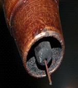
ROBOT WELDS AND TUNGSTEN CONSIDERATIONS:
 To
establish the TIG arc, the TIG power source provides high frequency (HF). The
HF ionizes the argon gas which improves the weld gas conductivity before the TIG
weld current is applied. With TIG it's important that the tungsten does not make
contact with either the part or weld as tungsten contamination can occur. Tungsten
contamination will "lower" the melting temperature of the tungsten causing
the tungsten end to ball or oxide, this reduces the plasma focus, direction, stability and also changes the TIG plasma profile. To
establish the TIG arc, the TIG power source provides high frequency (HF). The
HF ionizes the argon gas which improves the weld gas conductivity before the TIG
weld current is applied. With TIG it's important that the tungsten does not make
contact with either the part or weld as tungsten contamination can occur. Tungsten
contamination will "lower" the melting temperature of the tungsten causing
the tungsten end to ball or oxide, this reduces the plasma focus, direction, stability and also changes the TIG plasma profile.
For these reasons;
[a]
All persons who handle the tungsten should use clean gloves.
[b] Only
grind the tungsten on a dedicated grind wheel.
[c] Do not use a tungsten
if grey - black oxide is evident on it's surface. Break off the contaminated part and regrind.
[d] Program the robot so the tungsten is a minimum of "0.060" at
the weld start, and "0.070" at the weld end.
[e] At this time
you are changing the tungsten every 50 parts. If you contaminate a new tungsten
on the first part you will have a high probability of extensive weld rework. Cut
a window in the robot door cell door, program the robot home position so the TIG
gun nozzle and tungsten is always visible to the robot operator.
PROVIDE A TUNGSTEN STICKOUT GAGE:
[F] I provided the robot operator with a
tungsten gage. At any time the operator can stop the robot when it's at the home
position, and without entering the robot cell, reach through the access window
and replace and reset the tungsten. The tungsten stick out from the nozzle should
be maintained at 6 mm.
TRAINING TRAINING TRAINING:
Your programmer needs more robot program training. In a plant such
as yours you also should have a second individual that can step up to the programming
plate if the programmer is busy or absent.
Each robot weld program should be clearly identified in the program, and each
program should be saved on a disc. The manufacturing or maintenance manger should keep a copy
of this disc in a fireproof box.
WELDING PROCESS CONTROLS:
Once
the program you have is calibrated and fine-tuned, a large weld process control
board should be mounted outside the robot cell. The board should identify the
parts, each weld and the weld data used. As the key weld parameter is weld current
you could use a large amp-meter attached to this board so your customers can see
that the current you set for weld number 5 is the current attained on the amp
meter. Personnel responsible for programming should realize that this process
control data should be maintained.
At the start of each shift and after
lunch part of the weld process control instructions should be, operators;
[a]
Check the gas cylinder contents and flow. Consider a bank of four cylinders so
you will not run out of gas.
[b] Install new tungsten; use the tungsten
stick out gage.
[c]
Perform a TCP check.
[d]
Weld the first part then have the programmer or supervisor provide a signature
stating all welds are OK or adjustment required.
PLEASE ESTABLISH WELD PROCEDURES:
At this time I believe you have "no
pre-qualified weld procedures". From a product liability perspective this
could be a serious issue. Also from a customer or ISO perspective what happens
when one of your customers asks to see your weld procedures?
CONCLUSION: As this report indicates extensive issues were generated. To
get to the root cause of the production problems each issue had to be identified
then rectified. As the issues were numerous and my visit only two days, I missed
an opportunity to really optimize your process to its peak capability. However
with the changes I made and the recommendations of this report you will have the
opportunity for dramatic improvements.
Contractual
and Vendor responsibility. As you are aware from this experience, you cannot depend
on vendors of equipment for specific process or application expertise. However
when purchasing automated equipment it's beneficial if you ask the vendor the
"right questions". It's also beneficial on future automated equipment
purchases to stipulate in the purchase contract that a production run of four
hours should be provided to prove the equipment and process. Also ensure that
the product literature, programs, training and equipment provided are really applicable
to your needs.
By the way your senior management and engineers may want to look in the mirror and ask a simple question. "Why in the robot purchase contract did you not stipulate that this robot weld quality - production be proven at the robot integrator before you would accept delivery and pay for this robot? Also why did you let the parties involved Fanuc - Lincoln and the integrator, walk away from their application failure without cost repercussion?
Regards Ed .Craig.
Some of Ed Ems Craigs Robot Weld Projects
.
BETTER THAN TIG.
WITH THOSE ROBOTS USE TIP - TIG:
If you want the highest TIG weld quality and productivity attainable with eith manual or robot welds, the regular TIG process is a poor choice, you should instead be looking at the above process that I and my buisness partner Tom O'Malley bought to North America.
This unique process is called TIP TIG, and it's weld quality and productivity potential is far superior than TIG - TIG Cold Wire - TIG Hot Wire. Tip Tig also dramatically reduces the typical TIG arc length sensitivity concerns which is especially a concern with TIG robot welds. Check out Tip Tig at www.tiptigusa.com. Tell them Ed sent you.
The weld report below deals with robot TIG welding issues that were occurring on one of the big three car parts. Each part required approx. 15 precise small welds and the the parts weld seams were later brazed. The TIG welds were made with a Fanuc Arc Mate 100 robot, and a Lincoln 350 amp "pulsed" square wave power source. The weld issues at this tier one part supplier were extensive. For more than a year they had struggled to attain a production rate of only 40% of what they desired. The tack welds were frequently missing. Arc starts issues were extensive, and the tack welds would leak.
|
.
.
This site provides the worlds best TIP TIG and TIG weld process control training and data.
TIP TIG EASY TO SET UP FOR A ROBOT OR A BUG-O.
.
.
.
.
ROBOTS AND THE LACK OF WELD CALIBRATION:
IN THE 1000 PLUS PLANTS I VISITED IN 13 COUNTRIES, I NEVER MET A MANAGER OR ENGINEER THAT WAS AWARE OF THE COMMON "LACK OF CALIBRATION" ISSUES THAT HAD BEEN OCCURING WITH THE MAJORITY OF MIG WELDING ROBOTS THAT WERE SOLD FROM THE 1970s TILL TODAY.
IT SHOULD NOT BE A SURPRISE TO THOSE THAT VISIT THIS SITE, TO FIND THAT LACK OF CALIBRATION OR POOR CALIBRATION IS STILL A MAJOR ISSUE WITH NUMEROUS MIG WELDING ROBOT CELLS IN 2015.
.
 A prime benefit of robot cell is supposed to be that the robot has the the potential to create "consistent - uniform weld results." A prime benefit of robot cell is supposed to be that the robot has the the potential to create "consistent - uniform weld results."
For at least 15 years, from the 1980's till at least 1995, with the majority of robots the robot pendant weld data and the weld power source output data was rarely calibrated or not calibrated correctly. You would have thought this would have been a major issue with the arc welding robots that were shipped to companies like GM - Ford - Chrysler - Honda - Toyota - VW - Mercedes - Volvo - Fruehauf. The calibration issue has had extensive influence on the MIG weld quality daily attained. However the reality is it typically meant little to the engineers or mangers responsible in these plants, as few understood the MIG wire feed - voltage - weld transfer mode settings, parameter ranges & relationships. With most of these weld decision makers, if there was a MIG weld problem in the robot cell they expected their programmers to "play around" with the weld controls.
As for the primary robot manufacturers and integrators who provided the robot equipment, the bottom line was robots was their business, and the majority of these guys lacked the process control - best expertise required with the proces attached to the robots.
The bottom line for most plants, was the robot programmed MIG weld data should have been made to mirrow the "pre-qualified written MIG weld data.
When two new robots are placed on the weld shop floor, and the programmer inputs in the pendant the MIG wire feed rate or current, both robots should then deliver that weld current within ___%, the weld voltage within ___% or the wire feed within ___% of the actual data thats programmed. Could you fill in those % blanks. That information is in my Robot Training program and that info should also be in the robot purchase contract and then verified by you the customer.
Remember MIG weld fusion or weld burn through is often influenced by weld profile changes of a few thousands of an inch. This is why it's important that at least the weld parameters provided to parts be consistent, and also remember that there is little value in a qualified weld procedure when the robots do not deliver the data that was part of the procedure.
.FOR THOSE FEW MANAGERS THAT BELIEVE IN ROBOT WELD PROCESS CONTROLS AND BEST WELD PRACTICES.
No company can be expected to apply uniform manufacturing weld practices and attain consistent weld quality results when they have robot weld calibration issues.
If for example with a MIG weld, the measured actual robot 0.035 (1mm) wire feed rate was 600 in./min and the robot pendant data
shows that a wire feed of 700 in./min was programmed, then weld quality simply becomes a joke.
Or lets say, instead of a wire feed settings, that 250 amps may have been programmed in the robot pendant, and yet only 200 amps was deliverd at the weld, then again, what's the point of spending money on weld procedures, a quality department, or a quality program?.
By the way the fact that the Japanese typically use MIG weld amps instead of wire feed rate as their prime robot MIG weld setting, this simply shows how little Japanese robot mfgs understood that with the MIG process there has always been one important constant for weld quality and productivity, and that constant was the "wire feed rate".
Eds 7 Steps to Robot Process Control Training Program
deals with this
important subject.
ROBOT WELD APPLICATION:
.
I was requested to come to this plant to resolve Panasonic robot issues. Panasonic had for years had major calibration issues and from my experience with them was that they had poor understanding of the requirements for a MIG weld. One Panasonic robot had the wire feed set at 350 IPM which delivered 200 amps, and the other Panasonic robot (purchased as a pair) that was welding the same parts, had it's wire feed also also set at 350 IPM and this robot delivered 175 amps. The result was parts were showing lack of fusion in their welds.
Most robots also have poor weld voltage calibration. For example, program 29 volts into
the robot pendant, out pops 25 volts from the power source. On the robot in the next cell that 29 programmed volts delivers 27 volts. With voltage variations you get weld energy variations, weld spatter issues, and possible weld transfer mode changes.
ANY COMPANY THAT PRODUCES MIG WELDED PARTS AND DOES NOT PROVIDE THE WELD CONTROLS NECESSARY TO ENSURE THE REQUIRED WELD QUALITY, IS A COMPANY THAT LEAVES ITSELF OPEN TO PRODUCT LIABILITY CONCERNS.
FOR THOSE FEW MANAGERS THAT WANT TO IMPLEMENT WELD PROCESS CONTROLS AND BEST WELD PRACTICE PLEASE NOTE:
IT
'S IMPOSSIBLE TO IMPLEMENT EFFECTIVE ROBOT WELD PROCESS CONTROLS
WITHOUT ROBOT - WELD EQUIPMENT CALIBRATION..
Managers take note: THE TIME TO DEMAND CALIBRATION IS IN A PARAGRAPH WRITTEN INTO THE ROBOT PURCHASE CONTRACT. FOR THOSE THAT FORGOT TO ASK THE INTERGRATORS OR ROBOT COMPANIES TO CALIBRATE THEIR ROBOTS, I WOULD RECOMMEND THE FOLLOWING.
Contact the robot supplier and tell them to get their rear ends asap to your facility AS THAT COSTLY ROBOT INSTALLATION IS NOT COMPLETE TILL THE DATA IN THE ROBOT
PENDANT (WIRE FEED, CURRENT AND VOLTAGE) AND THE WELDING POWER SOURCE ARE CALIBRATED, AND PROVIDE THE SAME RESULTS IN ALL YOUR ROBOT CELLS.
Managers note: That annual check of the MIG power source amp - volt readings by your maintenace department is not what we are talking about..
.
|
.
"Robots and Programmer Weld
Process Control Expertise".
A people question from an HR manager at a large manufacturing facility that utilizes MIG welding robots
Ed. What type of "MIG Weld Process Control Expertise" should we expect when we hire a new robot programmer who will be in charge of our MIG welding robots?
Answer.
Your anticipations in 2015 to hire a person with robot MIG weld process controls - best practices expertise needs to be very low, the reason is less than 1 in 50 persons who program MIG robots for a living will have the necessary optimum process control best practice expertise.
It would be beneficial if the robot programmer was able to do the following.
Lets say the weld application is a Robot MIG welded common, carbon steel, automotive part. The parts welded are 2 to 2.5 mm thick with gaps 1 - 2 mm. Most of the gage welds are simple fillet - lap welds. The programmer is informed that the last time your company welded similar parts, that weld burn-through issues were prevalent. With this situation, a programmer should know without "playing around" to instantly set all the optimum robot weld start - weld - end parameters such as the wire feed, or the amps, the weld volts and the weld travel rate. The programmer should be aware of the best gun angles, weld techniques and weld practice solutions that can minimize robot down time or instantly rectify any weld issues.
A good robot programmer would be able to justify and explain the benefits of the weld transfer mode, the weld gas and the weld wire type or size selected. That same progranner would then be able to train the cell operators to recognize arc sounds that indicate weld faults and train them on what a good weld and bad weld looks like..
A robot programmer should have the capability without playing around and without"reference to a MIG weld text book to instantly;
[] Provide the most logical mode of weld transfer, short circuit, spray, globular or pulsed and be aware of the optimum working parameter range is for the wire size and weld gas utilized.
[] Provide if using pulsed, expertise on the wide variety of pulsed parameter adjustments and also be aware when and when not to use pulsed.
[] Provide the maximum robot weld travel speeds for each weld.
[] Provide weld voltages for each weld that will minimize weld spatter and cleaning.
[] Be aware of how to minimize the effects of the weld heat on the part and how to prevent bot distortion and weld burn through.
[] Provide the optimum robot weld start / stop data.
[] Be aware of the robot MIG gun technique which can effect the welds.
[] Provide weld data that compensates for gaps or part alignment discrepancies.
[] Provide weld data that ensures consistent weld fusion with minimum porosity.
[] Be aware of the weld deposition rates that can be attained and their influence on robot weld travel rates and the weld cost,
[] Be able to educate the fixture manufacturers and designers of welded parts on how to design for good weld ability
Be able to answer my MIG weld questions.
A SMALL PRICE FOR KNOWLEGE: To train yourself or robot personnel with all of the above data costs the whopping sum of approx. $300. You will find it my manual or robot process control training resources.
|
.
.
How many companies could relate to the following?
 The robot parts have unacceptable "weld gaps". Weld gaps outside the design criteria simply result from managers and engineers that don't know how to do their job. The robot parts have unacceptable "weld gaps". Weld gaps outside the design criteria simply result from managers and engineers that don't know how to do their job.
Weld gaps are the number one problem for "robot" MIG welds. Managers, designers and engineers frequently forget that manual MIG welders typically will utilize manual techniques, dexterity and skills to compensate for their weld gap variations.
With the blind, dumb robots working with weld gaps that were not on the original parts, it takes an understanding of MIG weld process controls, an understanding of best weld practice for the weld mode used and for the application, and it also takes sophisticated robot programming, and sometimes complex joint sensing controls to provide solutions to those variable an inconsistent weld gaps.
It's a fact that in most automotive - truck plants, that too many weld part dimension tolerances are not in accordance with the part design tolerances. I believe that acceptable, maximum, dimensional weld gap tolerances for optimum, gage (<2.5 mm) MIG robot welds would typically be 0.060m (1.6mm). This dimension is acceptable even for thin gage metals up to 0.060. With very thin gage parts that are less < 0.060, the weld gaps should be no larger than the gage thickness.
In contrast for fillet welds on parts > 3mm, there should be no reason that the gaps should be no more than 0.020 - 0.030 as lack of side wall fusion is readilly attained. As most designers of welded parts have no interst in the weld process used on ther parts you will find that real world weld dimensional weld gap tolerance are rarely known by the designers.
To compensate for the common oversize weld gaps on the thin parts, the automotive manual welder who rarely touches their power source controls, develops "reactive welding skills." The welder can increase the welding wire stick-out to compensate with a weld current reduction. In contrast the robot requires programming that utilizes logical best weld practices and techniques, or uses different weld parameters and weld schedules to compensate for the gaps. This subject covered here.
|
.
 You will frequently see "long MIG Wire Stick Outs over one inch" ( > 25 mm) used in automotive - truck plants and where high deposition welds are required. You will frequently see "long MIG Wire Stick Outs over one inch" ( > 25 mm) used in automotive - truck plants and where high deposition welds are required.
Manual MIG welders welding thin exhaust parts with excess gaps will often utilize a long MIG wire stick out in the range of one to three inches (25 to 75 mm). The reality is that any company that allows manual MIG welders to weld on gage parts with more than >25 mm wire stick out, this is a company waiting to be sued for poor weld quality and poor quality parts.
The first practical solution to welding gaps is place a little focus on providing training for manufacturing engineers and supervisors so they can build the stamped welded parts in accordance with the part design dimension tolerances, then provide the MIG process control training program so the issues are dealt with in a professional manner..
.
What width should lap
slot welds be on Robot welded gage parts?
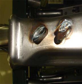 Note the poor design slot dimensions of the these car seat, robot slot MIG welds. These slot are simply "too wide" and a slight issue with the robot TCP or wire helix problem, and the weld will miss or burn the slot edge. Also the short weld lengths typically produce erratic, poor quality weld results.. Note the poor design slot dimensions of the these car seat, robot slot MIG welds. These slot are simply "too wide" and a slight issue with the robot TCP or wire helix problem, and the weld will miss or burn the slot edge. Also the short weld lengths typically produce erratic, poor quality weld results..
Note the weld differences thoe the same robot weld data was used. The inconsistencies in short weld lengths is common with electronic pulsed MIG equipment.
Any slot wider than 2.5 mm on gauge parts will reduce weld productivity (larger weld sizes = slower weld speeds), increase weld burn through potential and with a slight movement of the robot TCP could reduce the weld strength.
Design errors such as this are too common and an indication that the designer of these parts did not understand the MIG process.
My advice would be to keep the slots at a maximum width of 2 - 2. 5 mm. With my slots no robot weld weaves would be required and the welds which should be around 3 - 4 mm in width will connect to both sides of the slot resuling in a stronger weld.
Note with any robot MIG weld lengths less than 3/4 (<18 mm), it would be difficult to define the weld quality that can consistently be attained. The reason for the short weld length concerns is the robot in a very short weld cycle time of typically less than 5 seconds will have to communicate three sets of
Weld Start
Weld
Weld End
The data required for optimum control of all gage welds is attainable from my weld process controls - best weld practice programs.
WELD PROCESS CHOICES FOR SHORT WELDS: To optimize short weld lengths, avoid weld burn through on common 1.2 to 2.5 mm gauge parts, and optimize the robot weld productivity, the programmer could utilize high short circuit parameters, moderate pulsed parameters or on the thicker gage parts low spray transfer parameters. If as a weld programmer you look at the above common part, and you don't know the optimum weld parameters for each of the mentioned weld transfer modes it's time to examine your expertise and your value to your organization.
|
.
Can you give him an hour while he
plays around with the weld controls?

| For more than two decades, the USA had a short supply of good robot welding fixture builders. And in 2014 there are few builders that understand the MIG process that welds parts on their fixtures. |
How many robot fixtures have you seen which do not allow optimum MIG gun access or optimum MIG gun angles?
How many fixtures have you seen that have clamps that don't hold the parts with sufficient rigidity, or the clamps are too difficult to open?
How many fixtures have you seen that are sensitive to weld spatter and need rework after being in operation for a few days?
How many fixtures have numerous manual operated clamps when a simple pneumatic control would open all?
For thin gage welds, you could reduce those weld burn through issues, if the fixture designer would think "heat sink" and add highly conductive alloys to the clamps and fixture in the weld vicinity. Weld part designers should communicate with fixture designers and both these individuals should communicate with the robot programmer.
A common management influenced issue in many manufacturing plants that have purchased MIG robots is "ineffective communication between all the parties involved in the robot weld projects" |
Panasonic Robot Concerns.

For six weeks the Panasonic robot team could not get their
ROBOTS TO PRODUCE TWO SIMPLE EXHAUST WELDS.
|
For me, it was another one of those annoying Japanese, Panasonic robot applications. Thanks to the Panasonic engineers, and their obvious lack of understanding simple weld application requirements, we had another simple weld application made complex for the robot end user.
After six weeks, the Panasonic engineers and Panasonic robot integrator could not get their robot to consistently place two small controlled welds, 15 mm in length. The welds were made on a carbon steel rod to a thin gage galvanealed part exhaust bracket. The exhaust hanger bracket was poorly designed by engineers at Honda however was weldable. The Panasonic robot personnel had given up on the project and left the plant and the part supplier had five days left before production was supposed begin. For the rest of the story click here.
|
HOW FAST OR HOW SLOW SHOULD THAT WELDING ROBOT GO?
 Most robots for two decades have been under utilized, and from a weld speed perpective they rarely weld at their weld speed potential. In contrast many other robots are welding at speed which are too fast producing welds with innsufficient weld fusion. Most robots for two decades have been under utilized, and from a weld speed perpective they rarely weld at their weld speed potential. In contrast many other robots are welding at speed which are too fast producing welds with innsufficient weld fusion.
The robot weld speeds can be influenced by;
[a] the wire size or gas selected,
[b] the shape of the part, the part thickness, or the part surface,
[c] the parameters or weld mode selected are not optimum,
[d] using pulsed when they should be using spray.
[e] using short circuit or globular, when they should be using pulsed or spray,
[f] perhaps its the fixture design, the part design, the joint type, part thickness or ridiculous gaps,
[g] maybe the weld size could be reduced.
In my MIG and Flux Cored Weld Process Control self teaching - training resources you will find all the information required for optimum robot weld speeds for all your applications. In my management book I provide unique research infomation that i carried out, that allows robot weld speeds in the 40 - 80 inch/min range.
For two plus decades, I had to reslove numerous robot weld
issues created from the poor Motoman MIG equipment.
|
 The following is an E mail sent to me March 2001. At the persons request, I have deleted his and his companies names. The following is an E mail sent to me March 2001. At the persons request, I have deleted his and his companies names.
Ed, we are on our 4th generation of Motoman robots, and I didn't think they could get any worse, however I was wrong.
I simply would not recommend the new UP/XRC Motoman robots to anyone. We have had nothing but problems with them.
Motoman has a real problem with the encoders in their motors, and we have replaced everyone at least once. In addition, I have a servo pack or motor go out on an average of once per week. They are also having wire harness problems with the insulation prematurely wearing out. I have had to replace four so far, and we have only been running since August. We have also had to replace 13 boards in the main processor. They are saying that the Panasonic power sources are creating noise in the unit and taking out the boards, but we are not really buying it and neither is Panasonic. Now, let's compare this to our Canadian facility which uses mostly Fanuc on the same lines designed to produce the same product. I spoke with their technical manager last week and he has not had any warranty claims since startup. If you total up what would have been my repair expense, if the robots were not under warranty, I would have spent in excess of $175,000.00.
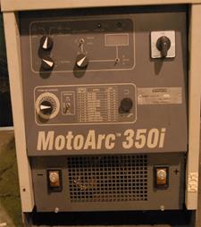
2003. Motoman also produced a sad excuse for a weld power source to be used with it's robots.
Notes from Ed: From 1985 to at least 2000, the majority of the global pulsed MIG equipment produced did not have the electronics necessary to provide controlled pulsed MIG transfer and with common steel and alloy steel welds this equipment often caused more weld quality = productivity - down time issues than it resolved. Unfortunately the weld equipment manufacturers forgot to tell the welding industry this simple fact. For more info evidence link here.
If you company used Motoman robots, it's unfortunate that you may have purchased the MotoArc 350 MIG weld equipment. If you were welding thin gauge steel parts with this power source and you wanted poor to mediocre, inconsistent, globular type short circuit welds, you purchased the right equipment.
|
This was not fit enough to be a toaster,
never mind a MIG power source.
If you wanted to produce poor to mediocre, inconsistent, globular type short circuit welds, purchase the above Motoman MIG power souce.
|
Erratic Volt - Amp with optimum weld settings.
FEW WELD SHOPS RECOGNIZED THAT FROM THE 1985 TO 2005, THE ELECTRONICS IN MOST THE PULSED EQUIPMENT COULD NOT MEET THE DEMANDS TO CREATE CONSISTENT, STABLE PULSED WELD TRANSFER. |

IF MANAGEMENT DOES NOT TAKE RESPONSIBILITY AND OWNERSHIP OF THEIR ROBOTS AND WELD EQUIPMENT, OF COURSE THEY SHOULD EXPECT WELD QUALITY - PRODUCTIVITY ISSUES.
Your company purchased a costly robot cell, yet because those that managed the robot purchase did not stipulate the correct questions on the PO, the robot integrator did not apply the appropriate tests to prove that the robot could consistently produce, optimum weld quality - productivity. Or perhaps your company did stipulate the correct questions on the PO and the robot integrator was simply incapable of the task.
From lack of essential calibration issues, to poor arc command response times and erratic poor performing MIG weld transfer modes, for more than two decades the major robot manufacturers like Motoman - Panasonic - Fanuc - Cloos and ABB selected MIG welding equipment that was the root cause of many of the global robot weld quality and productivity issues that were common throughout the weld industry. However the good news for the robot and weld equipment manufacturers, was thanks to the general customer MIG weld process ignorance which was especially common in auto - truck plants, few company managers using the poor performing weld equipment recognized the real root causes of many of their weld issues. Therefore few managers or company owners took legal actions against the robot and weld equipment suppliers for their weld quality cost issues and production losses. The common robot weld problems I had to deal with;
[] Poor power source characteristics.
[] Slow power source to robot communication.
[] Poor weld parameters selected.
[] Poor choice of consumables.
[] Poor robot / weld equipment calibration.
[] No best practices or process controls.
[] Lack of weld process expertise by all involved.
Weld quality and productivity responsibility starts in the front office.
When I visit a plant I work with the robot programmer. After a quick assessment of the weld issues, I would then make the robot weld program changes necessary to compensate for the parts, weld or robot equipment inadequacies. My process changes always improved the weld quality and increased the weld production. After I create the new weld programs and check the welds, I then provide the process control training. As managers and engineers are supposed to be responsible (few are), I insist that all
management, engineers and supervision involved with the welds take part in the training.
When making robot changes, its frustrating to see with specific robots how slow those program changes are being made especially with Japanese robots. Keep in mind, I have worked with every possible global robot type. If you are a "job shop making frequent new robot weld programs" I firmly believe that the ABB robots thanks to the joy stick control and logical Swedish weld soft ware, will require with parts that have many welds, typically 30 to 60% less robot programming times
EVEN ONE OF THE WORLD'S LARGEST ENGINEERING COMPANIES ABB,
AND ESAB A GLOBAL WELD EQUIP MANUFACTURER DID NOT KNOW WHAT THEY WERE DOING.
As some of you are aware I was the North American weld manager at ABB robots. While I had much admiration for their robots ABB also had issue with the MIG weld equipment it utilized. ABB got together with ESAB to integrate an Erratic MIG weld power source into the ABB controls. The ESAB equipment marriage would result in the first robot system produced in which the weld power source and robot control would become a single unit. When the ESAB / ABB robot controls arrived in North America in late 1990's, I was responsible for testing the weld equipment and found numerous major weld issues with the ESAB equipment. The ESAB power sources had unsuitable slope dynamics for most MIG welds and irrespective of the optimum weld data used, the results were unstable, inconsistent, poor quality welds especially on parts > 3 mm. Even though the power source was built into the robot control, the weld parameter change response time was too slow dramatically impacting the control of weld starts / ends. The bottom line was the power sources sold by ESAB for the ABB robots was better suited to manual stick welding than for optimum robot MIG welds. The sales personnel at ABB could readily see the ESAB weld issues in the test lab. My blunt advice to the salesmen " if you want to get and keep your robot business, recommend the robots with Miller Delta Weld Equipment". ABB sold the units with the poor ESAB weld equipment to the USA industry and other users knowing the power sources were substandard.
WHY DIDN'T THE GLOBAL WELD SHOP CUSTOMERS COMPLAIN
ABOUT THE ROBOTS AND MIG WELD EQUIPMENT?
The majority of the ABB / ESAB weld power source units were typically sold in the auto plants that had little understanding of the weld process requirements for optimum MIG weld quality / productivity. Remember these were the companies that are used to and have through ignorance always lived with both manual and robot MIG weld quality - productivity issues. And lets face it, managers, engineers and supervisors who lack MIG process control expertise will think it's natural for their weld personnel to play around with the robots and MIG weld data. When you get a chance, visit the MIG equipment sections of this site to read about the sub standard performance of pulsed MIG weld equipment from 1980 to 2005. It's 2013 and while electronic advances are making vast improvements in PULSED MIG equipment performance, there is still little justification for this costly, difficult to maintain equipment and I still weekly see many of the same old problems.
|
More ABB Robot / ESAB Arcitec MIG Power Source Issues.
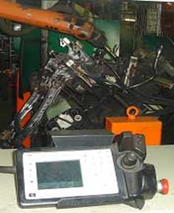
Poor Robot MIG Welds on Ford 6061 Aluminium Car Seats.
During 2000, I was requested by an engineer at VAW a tier one supplier, to evaluate the weld performance of their ABB robots and ESAB Arcitec weld equipment. This plant produces extruded aluminium parts. The aluminium welded car seats were for manufactured for Ford. The car seats and parts required small welds which were made on thin gage 6061 aluminium. Since the installation of the robot cells, continuous production of optimum weld quality parts has been impossible as a result of the weld issues documented in the following report. The weld reject rates averaged sixty percent and the robot down time per hour averaged 20 to 30 minutes. To see the rest of the ESAB Arcitec story, click here.
|
SOLUTION TO A COMMON ROBOT MIG PROBLEM.
"INCONSISTENT ARC STARTS"
Weld Solution Info like this in Craig's Robot Training Program..
Weld Question:
Ed, we frequently have poor robot arc starts on our MIG spray transfer, carbon steel or stainless weld applications. Often the arc does not initiate. We weld carbon steel parts 3 to 5 mm thick. The typical fillet weld size is 3/16, (5mm). For the 3/16 fillets we use an 0.045 (1.2mm) wire set at 450 in./min. The weld travel rates vary from 40 to 60 in./min. The gas used is an argon - 5% oxygen gas mix and the weld / start volts vary from 24 to 25 volts.
 Answer. The part thickness you weld and the 3/16 fillet weld size requirement allows " higher than normal manual weld travel rates". Weld speed affects the weld voltage used, the faster the speed the lower the weld volts. Two things here are effecting your weld start issues. The argon - oxy gas used requires" lower weld voltages" than the more common argon 10 - 20% C02 mixes. As the fast weld speeds require "lower weld voltages" and the gas requires lower weld volts "therefore the weld voltage you are using is lower than normal for the high wire feed rate delivered". Answer. The part thickness you weld and the 3/16 fillet weld size requirement allows " higher than normal manual weld travel rates". Weld speed affects the weld voltage used, the faster the speed the lower the weld volts. Two things here are effecting your weld start issues. The argon - oxy gas used requires" lower weld voltages" than the more common argon 10 - 20% C02 mixes. As the fast weld speeds require "lower weld voltages" and the gas requires lower weld volts "therefore the weld voltage you are using is lower than normal for the high wire feed rate delivered".
For starting the arc with the high wire feed used with the 045 wire, you typically would require 28 - 30 volts. Examine your other options below.
Robot Arc Start Solution: Just because you are welding with a high wire feed rate for the weld does not mean you have to use a high wire feed rate at the weld arc start. You could reduce the 0.045 wire feed rate at the arc start to a low spray rate of 370 ipm instead of the 450 ipm. This would require a lower start voltage of 26 to 28 volts. This action not only improves arc starts, it will reduce wire burn back potential and stop over size welds at the start.
Robot Arc Start Solution: For a spray weld ensure the arc delay time is sufficient for the arc ignition. Typically 0.2 to 0.4 seconds. Remember robot micro times are rarely accurate, if you don't hear your arc start data the time you selected is typically not effective.
Robot Arc Start Solution: The larger the weld the longer the arc ignition delay time. The smaller the weld the shorter the ignition time. On gage applications I rarely use ignition delay times
Robot Arc Start Solution: Ensure the pre-flow gas time is sufficient. Without gas ionization arcs don't exist
Robot Arc Start Solution: If you don't want to build up a glob on the end of your weld wire, remember that good arc start data requires good end weld data. Optimum weld end data ensures the completed weld wire stick out is minimum and there is no ball of weld on the wire tip.
Note: In these pages ee are touching a miniscule amount of the process control - best practice data that I provide in Ed's Self Teaching & Training Resources.
|
Lincoln Pulsed MIG Equipment and Robot Axle Weld Cracks.
|
 2000: If you want to make your weld manufacturing life more expensive, more complex and less meaningful than it needs to be, you could have listened to a salesman and then purchased a Lincoln Power Wave for your robot or manual MIG applications. Check the American Axle - Ford - Lincoln axle crack concerns in the equipment section, 2000: If you want to make your weld manufacturing life more expensive, more complex and less meaningful than it needs to be, you could have listened to a salesman and then purchased a Lincoln Power Wave for your robot or manual MIG applications. Check the American Axle - Ford - Lincoln axle crack concerns in the equipment section,
|
One of the worst pulsed MIG units developed in the USA by Lincoln. Typical erratic Powerwave pulsed MIG welds
on Ford Truck frame
MIG welds. (welds on the world's best selling trucks).
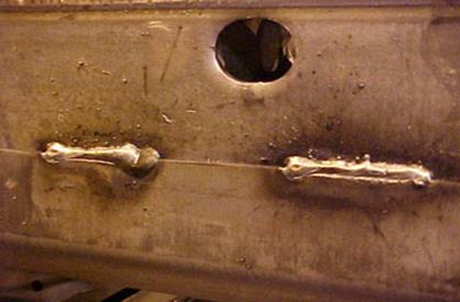
This was the norm for Ford whos management did not know better.
There were 6 major issues with the Ford robot frame "pulsed welds" made at a USA tier one supplier. The welds were made with an 0.052 (1.4 mm) MIG wire and a Lincoln Power Wave. Can you look at the welds and identify the process issues? Could you instantly provide the data to correct these sad Frame welds. All the process control data you need for optimum robot weld quality and productivity for any application is available in my low cost, CD training programs.
 Robot weld issues because sometimes in robot cells, "TIME accumulates. Robot weld issues because sometimes in robot cells, "TIME accumulates.
For robot welding small fillet / butt welds < 3/16 (< 5 mm) in size, it's often beneficial to use "No Arc Ignition Delay Times". A robot ignition delay time in combination with arc weld start delay time and the pre flow gas time can create too much of a delay at the weld start leading to a larger weld usually in the first 9 mm at the start, (look in the photo above). Remember the times put into that robot program our rarely accurate and can be much higer or lower than the programmer expects.
For two decades the timing issues have been an issue with all robots and needs more consideration from both the robot / MIG equipment manufacturers. Some robot manufactures believe their robots will provide the controls necessary for the weld starts and stops, while in contrast the MIG equipment manufactures believe their power source should provide these controls, it's been this way for two decades, Ying versus Yang, and screw the weld shop.
In contrast with larger welds as typical on parts > 5 mm, the longer the arc start times and pre-gas flow required. To establish the weld puddle with welds larger than 5 mm, an ignition delay time of 0.3 to 1 second. is typical. if you cannot hear the start time data change to the weld data your times are innefective.
Aluminium welds require long start delays, this is necessary to break up the aluminium surface oxides.
Note. In robot cells, often at weld starts, the most troublesome robot weld is often the very first weld, or a weld made after a long weld pause. The problem occurs because the welding wire is "cold", electrons travel better when the wire is hot. For this situation you may benefit from using a shorter wire stick out at these program points. Always have a least 2 robot arc re-strikes programmed for all welds.
Optimum Robot Spray Start Data for carbon steels with 0.035 (1mm) wire welds on parts > 4 mm. For the 0.035 spray weld arc start, set the wire feed at 500 in./min with 27 to 30 volts. This recommendation purposely utilizes low spray transfer wire feed rates, settings which require "minimum spray volts". The low wire feed rate and moderate (not too high) voltage is the best combination for weld start data. This weld data not only provides optimum arc starts it also reduces the potential for wire burn backs to the tip at the arc starts.
There are many factors that influence robot weld profiles at arc starts and at arc ends and these with the resolutions are addressed in all my robot weld process training books. resources.
.
|
.
 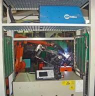
Robots and MIG equipment. Premature Interface Communication.
.
.
 Motoman - Fanuc Robot Weld Question. Motoman - Fanuc Robot Weld Question.
Ed I am a weld consultant. I came across a weld problem with Fanuc and Motorman robots. At the plant I was assisting there was a Fanuc robot which was 5 years old and it was utilizing a Lincoln Power Wave power source. The plant also had a Motorman robot which was brand new and the power source was a Miller Invision 11. The weld problem was notable on both 3/16 - 1/4 fillet, stitch welds. The welds were 2 to 4 inches in (5 - 10 cm) length and it would appear that 50 to 75% along the weld length the weld appearance would change. Ed what do you think is happening?
 Answer. What do you expect from North American designed MIG weld equipment that is trying to communicate with the land of Japan. Answer. What do you expect from North American designed MIG weld equipment that is trying to communicate with the land of Japan.
I believe you have a case of what I would term as PRC (Premature Robot Cmmunication). The poor interface with this equipment between the robot and power source has left it's mark on your welds. Instead of the robot going to the end of the weld and "instantly" bringing up the pre-programmed Weld End / Crater Fill data, your robots like many of us are premature and bring up the weld end data too soon. Try this, place an additional robot program point about 3 mm from the end of the weld and make sure you complain to that robot company or integrator as this is their SOFTWARE - HARDWARE issue, not yours..
There are many factors that influence robot weld profiles at arc starts / arc ends and these are addressed with many solutions in all my robot weld process training books.resources.
.
|
STAINLESS MIG GAS SELECTION & ROBOT MIG WELDS.
.

Robot Weld Question:
Ed, we robot weld 300 series stainless. The parts are 1.8 to 2.5mm used in an exhaust manifold. The parts have inconsistent fit and gaps. We have been using an 0.045 (1.2mm) wire with a 90% helium - 7,5% Ar - 2.5% CO2 tri-mix with short circuit. Many of the welds are lap welds with gaps and we often find the extremes like either lack of weld fusion
or weld burn through and always distortion. Are we using the correct consumables and which pulsed MIG equipment, would you recommend for this application?
Ed's Weld Answer:
First, stop wasting money on that useless Helium Tri-mix. This gas mix which requires the highest weld voltage along with other things is adding to your weld burn through - distortion issues. See my two part weld gas recommendations in the MIG gas section at this web site. The choice of 0.045 wire on these applications was not correct, the 0.035 wire with higher weld current density - and low to high current short circuit current capability would have been fine. However with this stainless thickness range, this is one of the few welding applications that can justify the use of pulsed MIG.
Reference the pulsed power equipment and consumables. I like the performance and price of OTC pulsed MIG equipment. Use the pulsed mode with an 0.045 wire, and use a simple but honest two part gas mix of 98 argon 2% CO2 which is suited to both pulsed MIG and short circuit. I developed this argon CO2 mix for the North American weld industry back in the 1980s, when I worked for AGA. The weld reality is most gas distributors are simply selling commodities they dont understand and they are either ignorant about the 2% CO2 mix, or they are happy that you are paying a premium for your poorly selected tri mix....
Using the pulsed mode will in contrast to short circuit provide superior weld wetting for the sluggish stainless thicker gage welds especially those welds > 2 mm. The higher pulsed wire feed rates than short circuit should also allow you higher weld travel rates than the short circuit welds which will decrease weld burn through and lower the weld cycle times and decrease distortion.
Remember when welding less than 14 gage or gage parts with gaps you can always switch back the weld transfer mode to short circuit. The argon CO2 mix will again benefit the short circuit as it will reduce weld burn through. As for that poor fit and inconsistent weld gaps in your parts I have a simple solution, fire the engineer responsible for those parts.
There are many factors that influence weld gas selection. If you visit the MIG gas section at this site you will note that I developed three of the major gas mixes sold in North America. Appropriate MIG gas selection without salesmanship is in all my Robot Weld Process Control Training Resources.
|
.
Drive Roll Groove Question: Ed I believe you need different guide rolls for different MIG wire types, what's recommended?. Thanks for your site, JH. Manchester UK.? |
.
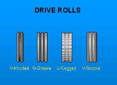
.
 Ed's Answer on MIG Drive Rolls: Ed's Answer on MIG Drive Rolls:
[] For solid hard wires use a Vee Groove rolls built for the wire OD. Two large rolls are just as effective a four smaller rolls. Note for MIG welds there is no MIG weld that should ever require using a wire diamter smaller than 0.035 (0.9 - 1mm)
[] For flux core wires use a Vee Groove with at least onE roll providing a serrated surface to improve the grip. Watch you do not apply too much drive roll pressure to these wires.
[] For aluminium wires use a U Groove with smooth surface again don't use excess drive roll pressure. With aluminium ensure minimum gaps between the inlet, drive rolls and outlet guides to avoid buckling. If using a regular MIG gun use a rigid plastic liner and when possible use a maximum gun length of 10 - 12 feet.
Note: The best MIG gun length for any difficult weld wire is a 10 foot length. What is the value of the free information that you are reading? Will you improve your companies weld quality - productivity and career prospects with the process control - best practices knowlege such as this? Visit Ed's Resources.
|

Robot Programmer asks a $alary Question.
03/23/2000: Ed, I have been working with robots for almost ten years. I am a highly qualified robot programmer. I have extensive MIG weld process expertise based over 20 years of MIG experience. As you are aware there are many career opportunities available to me at this time, particularly in plants that supply auto - truck, robot welded parts.
I have been looking at many different job opportunities mostly in the auto / truck industry. When I go for a job
interview, I usually find the plants will have numerous robot weld issues. All the plants I visit employ engineers
who obviously do not have the expertise to address the daily, costly, robot or weld issues. I know that I can improve their weld quality - productivity and have a big impact on these companies, however, and here's my gripe. When it comes to the salary offered no one offers to pay me more than they pay their entry level engineers who seem to have little influence on improving anything. The bottom line the salary offered is typically not much more than they pay their manual welders who work few hours overtime. By the way as a salary individual, the only time
I can make "major changes" to the robot programs is on the weekends. So on Saturdays and often Sundays, when the managers and engineers are at home, I get to work without over time pay alongside the hourly paid trades people who get time and a half. Rrgards and thanks for what you do. Mike James.
 Ed's Reply: Ed's Reply:
Mike lets face it. when you work for management that do not understand what you do, your remuneration and responsibilities will reflect this. The salaries today offered to the few, experienced robot arc weld programmers (programmers with process control expertise) in North America are not much different than 25 years ago, and in reality are a sad reflection of how out of touch the majority of engineering and manufacturing managers are from the real world requirements for optimized weld automation. Lets face it, to figure out how much your management will understand what you do daily is to take a look at the common two paragraph simple, job descriptions or perhaps like many technicians you wont have a job description. In automotive plants, where managers and engineers waste so much time daily running around putting out fires that they cause, you will typically find that weld quality and productivity responsibility is rarely clearly defined. In too many manufacturing plants that do a large amount of welds, hands off managers and engineers tend to shy away from weld process and equipment ownership.
It's a global weld reality that few manufacturing or HR managers are familiar with the expertise levels necessary for optimum robot arc welding process optimization. From a weld career perspective, If I was in your shoes and looking to improve my job satisfaction, increasing my salary and quality of life. I would look outside the auto industry to industries which offer a higher calibre of management for example manufactures of medical equipment or valves.
Today many companies use robots in the medical, defence, electronic, power and oil industries. With these companies in contrast to the automotive industry, you will typically find a more relaxed, intelligent approach to manufacturing, with better wages, shorter hours and less dead wood management.
|
.
WELD JOB DESCRIPTIONS
OR LACK OF, DEFINE
THE WELD MANAGEMENT EXPERTISE.
In many manufacturing plants where minimal focus or understanding is placed on the expertise necessary to attain optimum, consistent weld quality and productivity from a robot, all you have to do is examine the job descriptions to figure out the management awareness.
IF A JOB DESCRIPTION AND RESPONSIBILITY IS CLEARLY DEFINED FOR HIGH TECH INDIVIDUALS, THE WELD QUALITY - PRODUCTIVITY RESPONSIBILITY, ACCONTABILITY AND SALARY WILL TYPICALLY BE AS IT SHOULD BE.
For those technicians or engineers who understand how their daily functions have a great impact on the weld quality / production attained, and you are frustrated but wish to stay with your knuckle head employer, my message to you is simple, educate your peers as to what you do and show your managers with weld production and quality data the money you daily save your company. As for that working Sat - Sun for free, be a man take pride in your expertise and learn to say no when you think its relevant.
Remember in today's bean counters world, if you don't show the beans saved you have little value.
To help those mangers who wish to put things right and feel the need to actually manage what they are responsible for, I recommend my "Management Engineers Guide to MIG" book and CD resource
|
NEW TECHNOLOGY IS
OFTEN NOT BETTER.
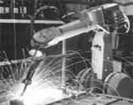 Hey folks you may not like the message, but you know you won't get this kind of info from your local weld equipment mfg or supplier. More practical robot weld data to follow I can write this stuff forever, but what the heck why can't you miss a dinner and invest in my books or in my self teaching CD training resources that way you have acess to the real valuable info that I don't provide at this site. Hey folks you may not like the message, but you know you won't get this kind of info from your local weld equipment mfg or supplier. More practical robot weld data to follow I can write this stuff forever, but what the heck why can't you miss a dinner and invest in my books or in my self teaching CD training resources that way you have acess to the real valuable info that I don't provide at this site.
If you were going to set a robot to weld inside a sophisticated vessel or container, I hope you would not set the MIG weld data like that shown in the ABB robot photo below. Remember for code quality welds that we now also have TIP TIG which provides superior weld quality and productivity than regular manual and automated Hot and Cold Wire TIG. TIP TIG is very compatible with robots and weld automation. (www.tiptigusa.com).
.
.
|
.
The Excess Spatter Window (a spatter window can be set for all welds)
reveals poor MIG weld parameter selection.

| This company purchased good robots but the weld sparks shows they lack MIG weld process control expertise |
MIG WELDS AND CONTACT
TIP ISSUES:
 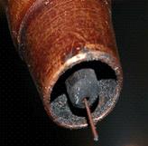 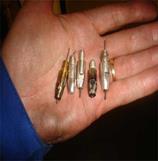
082007. E-mail:
Hello Ed. I recently purchased your "Management and Engineers Guide to MIG Welding book". The 600 page book is everything I had hoped it would be...and then some! The company I work for has a handful of welding engineers scattered throughout North America. Over the past few months I have had a growing number express satisfaction with using 0.030 tips with 0.035 wire robot welds. My issue is this, no one has given me a specific engineering or scientific reason for the contact tip change. Simply, "So-and-so told me to try it. It works for him so I do it to." (I believe the idea originated with a suggestion from one of the consumable sales reps.) This concerns me. I foresee a number of problems including increased uneven tip wear, restricted wire feed, spatter blockage issues, etc and I don't see where current flow would be influenced significantly.
Am I missing something? By the way Ed, thank-you for having the motivation and courage to make this kind of information available. I have not yet come across an opinion from you that I did not share or a concept I did not admire. Regards. Fraser Rock. Weld Eng:
 Ed's Reply: Fraser: Thanks for kind words. For the five decades I have worked with the MIG process I have never had to use smaller tips unless there was something wrong with the wire diameter or the tip bore dimensions, and in theses situations, i would change the supplier of the consumables. I have found in many plants that a common issue like this is usually a "distraction or crutch" for plant people (including engineers) who frequently lack the ability to get to the real root cause of their daily weld issues. Ed's Reply: Fraser: Thanks for kind words. For the five decades I have worked with the MIG process I have never had to use smaller tips unless there was something wrong with the wire diameter or the tip bore dimensions, and in theses situations, i would change the supplier of the consumables. I have found in many plants that a common issue like this is usually a "distraction or crutch" for plant people (including engineers) who frequently lack the ability to get to the real root cause of their daily weld issues.
Most robot contact tip issues typically result from wire burn backs, poor weld start and end data, incorrect wire stick outs, poor parameters or wire cast - helix issues. A contact tip bore needs to be approx. 0.008 to 0.01 larger than the max wire diam. When you purchase smaller tips than those recommended it's important to remember that with today's inconsistent weld wire quality, the weld wire OD is inconsistent and could be on the plus side. No contact tip should be put on a robot without the robot operators or weld personnel manually running the weld wire through the tip. If the wire and snags, the wire is too large or the tip is too small. If the wire is manually fed through the tip and makes consistent, unrestricted contact, it's fine. If the tip bore is not the correct size, (check with drill gauge), change your contact tip manufacturer, Remember that many of the contact tips sold in North America are made in China and you will find that like most Chinese products, the tip bore dimensions are often all over the place. If the MIG wire OD is too big, change the wire manufacturer and for god's sake get rid of weld distributor that provides you with these poor quality products.
As for those so called weld engineers. For the last decade, there has been in North America many weld quality issues with offshore manufactured, substandard weld consumables. The role of an engineer is not to provide BS or add to the numerous weld shop myths, but to get to the root cause of all welding issues. Regards Ed:
.
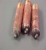 E-mail: E-mail:
Question: Ref MIG wire burn backs to the Gun Tip.
Ed, we are one of the largest producers in North America of automotive Shocks. I would say that our robots on average weld 200 to 400 parts per-shift. In each robot cell we average 2 to 5 wire burn backs per shift. The burn backs require that we frequently replace the contact tips. As the down time and time required to rectify the problem takes an average of 5 to 10 minutes per burn back you can imagine the production and weld quality consequences. What is the primary cause of this common robot problem, why does this not happen as frequently with manual welders, and are there practical solutions?
 Ed's Answer: There are many factors that influence weld wire burn backs and this is one of the prime causes of robot down time. These issues are easily resolved To quickly get to the root cause of all your contact tip issues, attain Ed's Robot Weld Process Control Training Resources. Ed's Answer: There are many factors that influence weld wire burn backs and this is one of the prime causes of robot down time. These issues are easily resolved To quickly get to the root cause of all your contact tip issues, attain Ed's Robot Weld Process Control Training Resources.
By the way I had one robot technician tell me the other day that he could not purchase my robot weld process control resources because his Tier One company that had paid over a hundred million dollars for it's robot weld line refused to pay the $390. Its a shame that a company that is likely loosing millions annualy with robot weld quality - productivity issues thinks like this. It's also a shame that the young engineer that likely spent at thousands on his weld education will not invest a few huindred dollars in attaining the real education he really needs so he can get away from those managers that have their head in the sand...
|
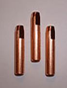 The so called MIG weld benefits from Special The so called MIG weld benefits from Special
Alloy Contact Tips for Robot Welds?
Ed contact tip issues is a prime cause of robot down time at our plant. We make steel auto / truck shock components. I figure each shift we are loosing 40 to 60 minutes of robot production per- robot cell due to the contact tip issues. We had a saleman tell us about his companies special alloy tips and their influence on tip longevity. My question is should we be doing more work on tip evaluation?
Signed Simon, a frustrated robot weld tech.
 Ed's Answer. Thanks to different alloy additions to copper of course some contact tips will offer different properties that can affect wear or conductivity, however and you can take this to the bank, the alloy composition of the tip is rarely relevant to the contact tip life. A larger, thicker contact tip does enable less weld heat to form in the tip in contrast to thinner tips. The real issue in most robot weld cells is to first recognize the root cause of the contact tip failure. You will find that most of the contact tips being replaced are due to wire burn backs and to weld spatter blocking the tip bores. Ed's Answer. Thanks to different alloy additions to copper of course some contact tips will offer different properties that can affect wear or conductivity, however and you can take this to the bank, the alloy composition of the tip is rarely relevant to the contact tip life. A larger, thicker contact tip does enable less weld heat to form in the tip in contrast to thinner tips. The real issue in most robot weld cells is to first recognize the root cause of the contact tip failure. You will find that most of the contact tips being replaced are due to wire burn backs and to weld spatter blocking the tip bores.
WHY LET ONE DOLLAR ITEM EFFECT WELD QUALITY AND PRODUCTIVITY?
Every robot operator should start each shift with a new, $1 contact tip and again replace the tip immediately after lunch. Each Technicain or Engineer responsible for the robots should at least twice a week, check the contact tip bore diameters and the quality of the tips purchased. The complete check list and my seven step program to prevent costly robot down time is item 4 and you know where that is. As for the special alloy tips if you continue to purhase them, give me a call, I have a bidge I can sell you in Brookyln for less than a $100.
Note: By the way, I created a patent on ceramic - Cu tips, and those tips were designed to allow extended MIG wire stick outs. This enables higher wire feed rates (faster weld travel rates) with lower MIG weld current.. These are two real world weld benefits for robot gauge welds. but don't go looking for them..
Robots and Gas Flow Issues.
Question.
Ed I'm having a hard time keeping flow meters from "blowing their lids" in my plant. We've run both ESAB and Rexarc flow meters and over time they are both failing. At the start of the weld the solenoid opens letting the gas flow into the flowmeter...pegs the BB out on the top of the unit then settles to the set flow rate. I have tried snubbers and I have tried placing the FM before the solenoid. We have 50 psi of 90%AR - 10%CO2 coming down from ceiling to each weld cell. Then provide a 10-15 ft flex hose to the solenoid. The flow meter is hard plumbed to solenoid, then 4ft flex to 8' Torch bundle. Do I need to rearrange? Is this common? Surely not! FYI, we have 2000 arc starts/day on these FM's, some last 4 months, others last 4 days! Should I remove the FM altogether and get a set calibrated orifice like at www.okcc.com? I did turn down my pressure leaving my gas mixer to 40psi but all FM's are calibrated at 50psi, so it throws off my readings. (Help)..
 Ed's Answer. Most MIG gas flow meters have the pressure regulated at 20 to 30 psi. I would install a pressure gauge at your outlets and lower your gas pressure to 20 - 30 psi. The only concern for MIG gas flow is the flow rate coming out of the MIG gun nozzle, and the robot operators should chaeck this at the start of each shift. This flow rate should be 30 - 35 cuft /hr. Ed's Answer. Most MIG gas flow meters have the pressure regulated at 20 to 30 psi. I would install a pressure gauge at your outlets and lower your gas pressure to 20 - 30 psi. The only concern for MIG gas flow is the flow rate coming out of the MIG gun nozzle, and the robot operators should chaeck this at the start of each shift. This flow rate should be 30 - 35 cuft /hr.
|
Question. WELD POROSITY:
Ed we have an extensive porosity issue with our robot welds would appreciate your thoughts on the subject.
 MIG WELDS AND POROSITY: What is weld porosity, it's a cavity, pore or many discontinuities that form in a weld from a gas and metal reaction. The porosity can trapped in the weld or at the weld surface. The porosity is typically round in shape but can also be elongated. The primary cause of porosity in auto - truck plants is lubricants on the parts and the result of fast weld speeds and poor weld data. MIG WELDS AND POROSITY: What is weld porosity, it's a cavity, pore or many discontinuities that form in a weld from a gas and metal reaction. The porosity can trapped in the weld or at the weld surface. The porosity is typically round in shape but can also be elongated. The primary cause of porosity in auto - truck plants is lubricants on the parts and the result of fast weld speeds and poor weld data.
ROBOTS AND MIG POROSITY. When you find the robot weld porosity occurs on each part at the same location, and it's not at the weld start or the weld end, examine the robot movement and see if the robot arm is causing a restriction of the gas flow line. Also it's common with robot cells to see a severe gas flow restriction due to the narrow orrifice gas line connections. In a robot cell it's critical that at the start of each shift that the cell operator measures gas flow as it "exits the gun nozzle". If the porosity is at the weld start or stop increase the gas pre flow and post flow times.
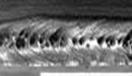 ALIGNED OR RANDOM WELD POROSITY. The common causes of localized or aligned group of gas pores with random distribution. If the weld surface is clean this porosity is typically a result of part contamination. If the weld surfcae is oxidized (grey) then look to insufficient gas flow issues. Also small weld lengths and small fast freeze welds and arc blow will contribute to this porosity ALIGNED OR RANDOM WELD POROSITY. The common causes of localized or aligned group of gas pores with random distribution. If the weld surface is clean this porosity is typically a result of part contamination. If the weld surfcae is oxidized (grey) then look to insufficient gas flow issues. Also small weld lengths and small fast freeze welds and arc blow will contribute to this porosity
ELONGATED WELD POROSITY. (Wagon Tracks). This porosity is typically found parallel to the weld axis. This classic porosity is evident when moisture is found in the gas shielded flux cored wires, (a too common issue). The pores rise to the suface of the welds, (usually in the weld center) and before they can pass into the solifying flux cored slag, the ores which can be large and small will form a rough line typically called Waggon Tracks. Increasing the flux cored wire stick out and increasing the wire feed rate will help. Storing wires in a dry environment also reduces potential. If however this is a common problem with the FCA wires change your FCA brand and change your supplier. The bottom line, avoid weaves and adding arc and weld energy decrease the weld cooling rate and should produce less porosity.
LARGE PORE WELD POROSITY. If weld surface is clean and does not look oxidized, the large pore MIG and FCAW porosity is usually a result of excessive gas flow. Gas turbulence occurs with gas flow greater than 40 cuft/hr and is especially prevelant in Vee - j groove welds.. If weld surface is grey and dirty, the cause is otfen a result of insufficient gas less than 20 cuft /hr. Gas flow must be measured at the gun nozzle.
|

.
.
The apathetic weld management at this tier one company, allowed the selection of an oversized, 0.052 (1.4mm) MIG wire for the robot frame thin gauge welds, below.
The hydro formed Ford Truck Frame welds shown are more than a bad welds, they are an indication of poor both poor weld management and company that does not understand weld process controls.
|
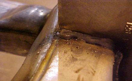
Can you identify the root cause
of these Ford truck frame MIG COLD welds?
A manager, engineer, supervisor or robot technician that had weld process control expertise would look at the above robot welds on the big three hydro formed truck frames, and instanly know what the weld issues and resolutions were.
The above tier one, Ford frame, globular welds with evident lack of weld fusion are not the fault of the robots or the over priced Lincoln Power Wave MIG equipment utilized. These and the other similar globular welds on the truck frames were the result of inexperienced, hands off managers and engineers who selected oversize MIG weld wires and used undertrained robot personnel to provide thousands of welds that jepodized the structural integrity with some of the world's most expensive truck frames.
|
Fanuc and Lincoln Power Wave.
  
and 2004 Ford 500 Cradle / Frame Welds.
Date 23. July 2004. 2004 Ford 500 Cradle / Frame Welds.. This report is a condensed review (changed with a little added humour too keep things sane) of a Ford robot weld line used to MIG weld the Ford 500 steel cradles and sub assemblies. I evaluated this new robot line to establish the root cause of the many weld issues that were impacting the cradle and frame robot weld quality and production.
This mid west, Ford plant purchased approx 100 Fanuc robots with Lincoln Power Wave weld equipment. The weld wire type was E70S-6, and size 0.045 (1.2 mm). It was notable the the Fanuc robots at this plant did not have automated TCP controls or any weld joint tracking equipment. The hourly production range was 60 to 70% of it's goal, and the daily weld rework was > 40%.
When purchasing robots for an auto or any high volume manufacturing facility, it's important that the management and engineers responsible do a weld risk assessment and that they understand how the parts or the robot equipment selected can impact either the weld quality or production. It was evident at this Ford plant that the manufacturing management and engineers responsible for the robot welds had little expertise or interest in owning the processes or the equipment that make their profits.
Note: With robot MIG welds, the primary concerns with common auto truck parts welding 2 to 4 mm is the attainment of acceptable and consistent weld fusion. Its a sad fact that on steel parts > 2 mm, one in three or four welds in the auto industry will typically will reveal marginal or lack of weld fusion. In contrast the weld concerns for parts less than < 2 mm, is typically to avoid weld burn through.
The Ford plant provided numerous welds on steel parts < 2 mm. On these parts the MIG weld burn through risk potential was high, and it was compounded by the poor weld data, oversized weld wire, unnaceptable part dimensional issues, plus lack of ability for the robots to track the weld joints, no control of the robot Tool Center Point (TCP), along with management and engineering process ignorance.
As the Ford plant ramps up to try and attain its 100% robot production goal, thanks to the apathetic engineering involved in producing stamped parts to the design dimensions, the reality is that it's unlikely that the part dimensions will improve, (most welded part dimension issues increase with amount of stamped parts provided). Therefore the weld issues, unless radically addressed will increase daily.
I found In this plant, that lke many, the weld consumable selection was influenced more by the purchasing department than by knowleable engineers, just as the robot and weld equipment selection for this plant has had more to do with salesmanship than it did with weld - robot engineering logic.
|
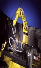
THE IMPORTANCE OF
ROBOT TCP CONTROLS.

THE FORD PLANT WAS LOOSING - 20 MINUTES/HR PER-ROBOT PRODUCTION LOSS BECAUSE THE FORD MANAGEMENT AND ENGINEERS LACKED THE BASIC KNOWLEGE NECESSARY TO ORDER THE CORRECT EQUIPMENT AND IMPLEMENT EFFECTIVE WELD BEST PRACTICES AND PROCESS CONTROLS:
Part dimension ACCURACY and TCP controls are critical when welding thin gage applications. The thinner the gage, the greater the weld gap sensitivity. Thin gage requires smaller welds which require faster weld speeds that require stable joint dimensions.
Torch Control Point (TCP), apart from maintaining the robot program point accuracy of the wire to work, also enables an altered program to be put back to the original approved program. In this Ford facility, with the robot cells purchased, there are no means for accurately checking the robot TCP, and you will find programmers constantly making changes to the welds, none of which have anything in common with the original so called pre-qualified weld program.
While I was at this plant, the plant typically was loosing slightly over 20 minutes/hr of robot down time. The lost production from the 33 robots in opertion (33 x 20 minutes = 660 min/ hr) The bottom line was each hour the plant was loosing > 30% of its production.
Note: On robot welded parts with gaps or inconsistent dimensions, to compensate, you typically have to be able to place "oversized weave welds". Over sized welds not only decrease weld travel rates, they can increase the weld burn through potential, especially on the 1.5 - 2 mm parts. To avoid weld burn through with the larger welds, aggressive weld weaves are beneficial, the plant programmers made no use of the weld weaves in any of the robot programs. Unfortunately with the numerous weld burn through issues, the resulting holes in the parts were disrupting the weld arcs, causing the weld wire to end up with excess length (excess wire stick out) which was a root cause for poor arc start and for the contact tip issues.
To minimize the potential robot weld issues that will occur, the Ford plant management needs more focus on the implementation of best robot weld practices and knowlege about process controls (cost a whopping < $300 at this site).
|
  
FORD AND THE LINCOLN PULSED MIG EQUIPMENT.
2004: For more than two decades, the major MIG equipment manufactures have been developing and promoting pulsed MIG equipment for "steel applications".
When so called engineers have to rely on "sales advice" for technical answere they get what they desreve. The Lincoln pulsed equipment purchased for your robot weld lines has undergone years of development, yet still in 2004 provides "poor arc stability" along with arc length sensitivity. The pulsed arc length sensitivity makes the pulsed mode unsuitable for most of your high weld speed steel applications. It's ironic that the weld equipment your company purchased has cost >50% more than the available superior, stable, traditional CV equipment that could have been used. The pulsed weld equipment purchased will also likely cost three times as much to repair and you will need to keep more spare equipment than normally would have been required with traditional, more durable CV equipment.
FORD AND THE PULSED MIG AND HIGH SPEED WELD CONCERNS:
When using an 0.045 (1.2mm) MIG wire and pulsed welding on the cross members, to attain the desired minimum weld travel rate of 45 ipm, on the 1.6 mm lap welds, the MIG weld wire has to have a "very short arc length" and virtually make contact with the weld surface. This required wire to work contact not only disrupts the pulsed transfer, it causes extensive weld spatter which negatively impacts the contact tip life. The weld spatter is also contaminating your fixtures causing part assembly and fit issues.
When establishing the Power Wave pulsed trim voltage, (the arc length) with this high speed pulsed application, if the pulsed weld voltage (arc length) is set to a none weld spatter condition, (requires increased arc length), the pulsed weld transfer and instability at 45 - 50 ipm weld travel rates will cause "skip welds" (missed welds and weld blobs on the parts).
.
Typically with this 2004 pulsed MIG power source technology, when pulsed welding we need a sufficient arc length to enable the pulsed MIG weld drops to form and transfer across an arc gap without making a short circuit contact with the work and with the wire tip. With the Lincoln pulsed MIG equipment selected the desired minimum arc length required for optimum pulsed weld transfers is detrimental when pulsed welding thin gage parts using 0.045 wire at the "high weld speeds". If logic and ownership had been applied by the Ford engineers, the weld equipment and the robots would have been tested before the purchase order was produced for the equipment and also the PO contracts should have stipulated that the weld quality - productivity goals be produced at least for 4 hours before the robots and weld equipment was delivered to Ford.
The thin gage parts also limit the allowed pulsed wire feed rates which limit the Lincoln Power Wave pulsed frequency utilized. The low pulsed frequency with the large wire diameters and a weld which for 50% of its time is at a background current of less than 100 amps resulted in an unstable weld transfer mode unsuited to high weld speeds on the Ford 500 cradle welds.
The robot, high speed skip weld issues at the Ford plant are the same pulsed weld issues that every wheel manufacturer and torque converter manufacture has had to deal with for almost two decades. Another ironic fact is when you use the Lincoln pulsed equipment in the traditional spray transfer modes which provides improved arc stability is the weld decision maker may not be
aware that the slope influenced performance of the traditional spray mode from the pulsed MIG equipment is typically inferior to the lower cost traditional CV equipment.
To attain high robot weld speeds with weld transfer stability, I recommend the pulsed mode should be replaced with the more stable, less arc length sensitive "spray transfer mode". While the spray mode runs hotter than the pulsed this is not a concern for the welds on lap welded parts in which the two parts combine for > 2mm. The the weld heat can be reduced through the use of
smaller MIG wire diameter such as an 0.040 or 0.035.
Note: Remember this time period is 2004 for pulsed MIG equipment, and although I had been describing these and similar pulsed issues on this site for at least seven years, managers and engineers in the auto industry were happy to get advice from the people who made and sold the equipment. Poor performing pulsed equipment was something companies like MIller. ESAB and Lincoln
did not discuss in public. There is not be the same pulsed MIG electronic and weld transfer concerns with most of the pulsed equipment sold > 2006.
CONCLUSION FOR THE FORD PLANT: I could waste my time and show you the numerous list of weld issues and the resolutions I provided for this plant. An ironic point also is Ford spends millions every year on training for robot weld applications such as this, and it's clearly evident that the management lack the technical ability to figure out the training that will attain the results they desire. I would hope that one day an intelligant, pragmatic Ford executive that sits in his ivory tower and does not have ego issues will read this stuff and will then come to the conclusion of where the responsibility lies and what has to be done.
|
.
.
 As I wrote the above Ford report, I was also involved with a tier one company that was using 0.052 (1.4 mm) weld wires on Ford truck frames that were typically 2 to 4 mm thick. This company was also using the same Lincoln pulsed MIG Lincoln equipment. They also went through the consequences of the pulsed arc instability, and they were unable to use high spray parameters required as a result of management selecting an oversize 0.052 wire. As I wrote the above Ford report, I was also involved with a tier one company that was using 0.052 (1.4 mm) weld wires on Ford truck frames that were typically 2 to 4 mm thick. This company was also using the same Lincoln pulsed MIG Lincoln equipment. They also went through the consequences of the pulsed arc instability, and they were unable to use high spray parameters required as a result of management selecting an oversize 0.052 wire.
As they could not dial in the required MIG spray parameters, the robot programmers at the plant unknowingly dialled in lower "globular parameters" which started to cause all types of production and quality problems, (see frame plant report at this site).The globular transfer caused over 80% weld rework. The globular drops on the wire tips also caused extensive robot down time.
A reasonable question that could be asked was which idiot at the Ford and Tier One company ordered the oversize 0.052 wire, and dont be surprised if the answer was found not in the management offices and engineering departments (no process ownership) but was found in the purchasing department.
July 30-04. E Mail to Ed. Ref Miller Pulsed MIG issues.
|
Miller Accu-Pulse / Auto Axcess Issues.
Ed: Your description of arc sensitivity with high speed pulsed welds is exactly what I am experiencing with our robots and the new Miller Accu-Pulse process / Auto Axcess.
The new auto bumpers we are welding are thin gage, 1/16 (1.6mm) HSLA and we have weld heat martensite concerns.
To minimize the weld heat into our parts, I tried to weld above 40 IPM with the Accu-Pulse using Miller's recommended weld settings we could not do the welds due to weld skipping and arc instability.
We went to an 0.035 wire and could not get the travel speeds so we changed back to 0.045 wire (1.2mm) wire and had to run the pulsed arc with the arc length buried in the part. The small arc resulted in extensive weld spatter, also the part could not handle the pulsed weld transfer and with the resulting high weld heat we had weld burn through holes all over the place.
With the disappointing Miller pulsed weld equipment results. we took your advice and changed the weld transfer mode to CV, using high circuit with the 0.045 wires. We are attaining 40 IPM travel rates and I have no spatter of any consequences on the parts. Also we are having no arc stability problems with the short circuit.m I hate to admit it but this is is another pulsed failure in my book. I am also pissed of at the fact that we could have got these short circuit weld results from much lower cost CV weld equipment without all the costly head aches.
Regards from a fan but a frustrated robot tech... G.S.
|
Please note I have not even touched the surface of the MIG weld issues that will occur in a robot weld cell, but I will tell you that I have covered the majority of the global MIG weld quality - productivity issues with the resolutions, in my Robot MIG Weld Best Practice - Process Control self teaching and training resources.
|