|
At www.tiptigusa.com, you will find a weld process that always produces superior weld quality than TIG, and is 100 to 500% faster. |
Welcome to the world's largest web site on MIG , Flux Cored and TIG. Weld Process Controls & Best Weld Practices. To get to the root cause of GMAW (MIG) & Flux Cored (FCAW) weld issues, requires Weld Process Control - Best Practice Expertise, & lots of Weld Reality. The site provides the MIG - Flux Cored and TIG weld information and data required to attain the highest possible manual and robot weld quality, always at the lowest possible weld costs.
This web site was first established in 1997 by Ed Craig. Contact Ed. ecraig@weldreality.com
Please "refresh" as changes are frequent.
www.weldreality.com
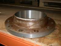
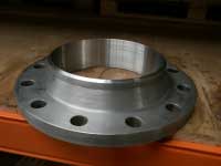
Welding Stainless - Duplex - Nickel Steels Data:
Note there is also a Duplex section.

.
E-mail. Question:Ed as we have a variety of weld process selections for stainless . What MIG and flux cored wires and weld transfer modes should we consider when welding stainless steel in the gage to 25 mm range?
Answer: The following primary weld considerations will influence the weld process required.
[] Distortion potential.
[] Cleaning and oxidation concerns.
[] Part thickness.
[] Weld positions.
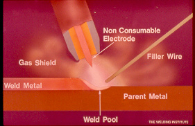
For any stainless or duplex weld on parts over 0.080 the TIP TIG process will provide superior weld quality with lower weld heat than any conventional manual or automated weld process.
When welding thin, < 2 mm, stainless steels, it's been traditional and logical to use use the regular TIG process, or MIG short circuit with an 0.035 (1mm) wire, however pulsed MIG is also an option.
ONE OF THE VERY FEW
PULSED MIG WELD BENEFITS:
MIG PROCESS ON SOME THIN STAINLESS APPLICATIONS.
In contrast to the MIG Short Circuit mode, you can with the pulsed MIG process, "if using weld automation", increase the stainless thin gage weld speeds, and also provide superior weld surface, (slightly more fluid). With the pulsed MIG gage welds, you will likely be using an 0.045 wire, for the gas mix, consider using the two part gas mix that I developed for stainless, it's argon 2% CO2, (see my MIG gas section). The pulsed MIG benefits are attained for stainless or duplex applications in the range of 14 gage to 3/16 thick .
MIG PROCESS FOR THICKER STAINLESS.
For stainless and duplex applications that are 3 to 5 mm, when welding "flat and horizontal welds", consider an 0.035 MIG or 0.040 wire when using the Spray mode. I recommend my Argon - 2% CO2 mix. For stainless parts thicker than 1/4 ( > 6 mm), consider an 0.045 (1.2mm) MIG wire with MIG Spray and also with Argon - 2% CO2.
Note: If the stainless or alloy weld heat is an issue for the parts, consider the pulsed MIG process using an 0.045 wire, and the same Argon - 2% CO2 gas mix. The back ground current from the pulsed mode will produce lower weld heat.
VERTICAL DOWN WELDS.
Keep vertical down MIG welds to parts that are less than 4 mm thick. Excellant control with vert down welds with an 0.035 wire and my Argon - 2% CO2 mix, with the low end of Spray parameters. Also may use pulsed MIG with 0.045 wires and the same gas mix.
VERTICAL UP OR OVERHEAD WELDS.To attain the desired MIG weld fusion when welding in the vertical position on stainless steel parts > 3/16 thick, (> 5mm) Weld vertical up or weld overhead welds, consider an 0.045 gas shielded flux cored wire with argon 20- 25% CO2. Do not use the gas shielded wires for "vert down" as trapped slag will increase.
Note: For those that insist on MIG welding vert down on > 3/16 parts, you may have lack of fusion issues.
Safety weld issues are a primary concern for anyone who welds stainless steels and nickel alloys...OSHA held hearings on it's proposal to reduce the PEL for hexavelent chromium from 52 micrograms per cubic meter to 1 microgram per cubic meter as an 8 hour time weighted average. By court order OSHA who should have been more concerned for weld safety was required to adopt a final rule by Jan 18. 2006. Click for MIG Welding Stainless Steel safety issues
Don't forget if you are concerned with attaining the highest alloy weld quality with no concerns for hexavelent chrome, take a look at a process my buisness partner and i introduced to America, its called TIP TIG . With TiP TiG you get the highest possible weld quality, the lowest possible weld heat and lowest weld fumes, and your TIG weld production should be increased in the range of two to six hundred percent.
.
.
.
MIG WELD STAINLESS STEEL, GAS MIXES AND WELD REALITY....
In the last three decades, the biggest selling gas mix in North America for MIG welding stainless steel, thin gage applications, has been a ridiculous tri-mix. This mix contains 90% helium - 7.5% argon and 2.5% CO2. In contrast to the three part helium tri-mix, a less costly, two part mix, argon - 2 % CO2, mix that I developed in the nineteen eighties, has always provided more thin gage, stainless weld benefits.
.
.
There are over 60 MIG gas mixes available for all MIG applications.
With these six MIG mixes Ed has defined
the world's most cost effective gas mixes.
.
.
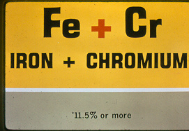
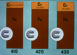
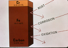
WHAT IS STAINLESS STEEL MADE OF?
STAINLESS STEEL COMES IN MANY FORMS.
Welding Stainless Steel Grades.
Austenitic, Martensenitic and Ferritic STAINLESS STEELS.
The Austenitic Stainless Steels are the ones most weld personnel are familiar with. These chrome nickel steels, in contrast to lower cost stainless have more alloys and are "non magnetic" (Exception, types 310 - 330)
Austenitic Facts: Austenitic grades typically contain a minimum of 18% chrome - 8% nickel (often called 18/8 steels).
Austenitic Stainless steel Grades 20-202-205-301-302-303-304-305-308-309-310-314-316-317-321-329-330-347-389-17 7PH- 17 4PH-PH15-7Mo-AM 350-AM 355 A 286.
Common Designations: 304 (S30400) - 304L (S30403) 316 (S31600) 316L (S31603) - 347 (S34700).
Stainless Steel Grades 301-302-304-305-308 usually welded with E308.
18/8 grades used for machine parts exterior buildings and industrial parts.Note: 18/8 grades are not to exceed 800F 426C service temperature.
Manganese stainless grades "200" series similar to Austenitic 18/8 grades.
Manganese in this series is used for "extra strength"
Welding the manganese grades usually requires the use of the E308L filler.|
Martensitic and Ferritic Grades are common stainless steel grades that we don't want to weld and if we do, we should weld with great caution.
Martensitic Chrome steels. Weldability, limited. Preheating typical 250°C to 450°C. Postweld treatment: Slow cooling to 120°C (martensitic transformation) and annealing at 750°C or hardening (generally 1000°C / oil), tempering (generally 750°C). Watch for formation of chromium carbide between 500°C and 650°C...
Note: When welding these grades the weld procedure concerns and focus will be on HEAT treat requirements.
STAINLESS STEEL WIRE INTERNATIONAL SPECIFICATIONS.
US AWS A5.9 / UK BS2901 / Japan JIS Z3321/ ISO 3581/ Germany DIN 8555 - 8556
UNS International filler metal numbers start with WXXXXX
.
.
Stainless Filler Metal Information:
Stainless
FillerInternational
SpecsChemistry Manufactures
designationsApplications Electrode
E308
Germany SG X5 Cr Ni 19.9
ISO 23.12
UNS W30940C 0.08
Mn 1 - 2.5
Si 0.25-0.6
Ni 9-11
Cr 19.5-22
Thyssen-Therm J
Kobe-MGS
Lincoln L18.8
Pacweld -PW176SS
Sanvik 19.9E308 is typically used when the corrosive conditions are not severe
Electrode
E308L
(low carbon)Germany SG X2 Cr Ni 19.9
ISO 119.9L
UNS W30843C 0.03
Mn 1 - 2.5
Si 0.25-0.6
Ni 9-11
Cr 19.5-22ESAB -OK 16.10
Thyssen -JE
Sandvik 19.9L
Note (L) designation.
The lower carbon is used to avert the formation of carbide precipitation
Electrode
308LSiESAB- OK 16.12
Thyssen - JESi
Sandvik 19.9LSi
Filarc - PZ6061/6561
TREFIL 2PPSG
Note Si or Hi Si.
designation.
The high silicon can increase arc stability and the weld wetting, which is important for some the low amp, sluggish, short circuit welds
Electrode
309
Germany SG X12 Cr Ni 22.12
ISO 23.12
UNS W30940C 0.012
Mn 1 - 2.5
Si 0.25-0.6
Ni 12-14
Cr 23-25ESAB- OK 16.53
Sandvik- 24.13
Thyssen -Therm 25.14
Used for welding 309 and austenitic to ferritic (carbon) steels
Electrode
309LC 0.03
Mn 1 - 2.5
SI 0.25-0.6
Ni 12-14
Cr 23-25Used for weld overlay applications, steel to stainless or for butter passes.
Electrode
310HC 0.10 -0.12
Cr 26
Ni 22(H) designation has minimum carbon content lower carbon can cause micro cracking causing tensile reductions
Electrode
310
Germany SG X12
CrNi 25.20
ISO 25.20
UNS W31040
C 0.08-0.15
Mn 1 - 2.5
Si 0.25-0.6
Ni 20-22.5
Cr 25-28To weld 310 and 304 clad and stainless overlay
For low or high temp, corrosive or any critical applications always confirm electrode choice with wire manufacturer. Using ELC, ensure weld gas has less than 3% CO2. A low co2 mix is less oxidizing than a low oxygen mix.For low carbon base use low carbon filler identified by EXXXL.
Electrode
312Germany
SG 9250XRC
UNS W31240
ISO 29.9
C 0.15
Mn 1 - 2.5
Si 0.25-0.6
Ni 8-10
Cr 28-32
Higher Ferrite.
More "crack resistance" than E309.Electrode
316Germany
SG9250ZRC
UNS W31640
ISO 19.12.2
C 0.08
Mn 1 - 2.5
Si 0.25-0.6
Ni 11-14
Cr 18-20
Mo 2-3ESAB- 16.35
Thyssen - Therm G.
Sandvik 19.12.2for 316 steels and good for "high temp" corrosion resistance
Electrode
316LGermany SG X2 CrNiMo 19.12
ISO 19.12.2L
UNS W31643
C 0.03
Mn 1 - 2.5
Si 0.25-0.6
Ni 11-14
Cr 18-20
Mo 2-3
Electrode
317L317 Germany SG CrNiMo 1813
ISO 19.13.4
UNS W31740
317L UNS 31743
C 0.03
Mn 1 - 2.5
Si 0.3-0.65
Ni 13-15
Cr 18.5-20.5
Mo 3-4Has moly to increase the tensile strength. Has excellent corrosion resistance and high temp properties Note contains considerable ferrite which can lower toughness properties.
Electrode
318Germany SG X5 CrNiMoNb 1912
Electrode
320
used for welding Carpenter 20 plus 20Cb-3 stainless
Electrode
321UNS W32140
C 0.07
Mn 1.43
Si 0.58
Ni 10.52
Cr 18.58
For weld data and information on Carbide Precipitation
scroll down to weld dataElectrode
347Germany SG X5 CrNiHb 1999
UNS W34740
ISO 19.9NoC 0.069
Mn 1.59
Si 0.49
Ni 9.96
Cr 20.82
ESAB 16.11
Thyssen Therm H.
Sandvik - 19.9Nbused for 321 - 347 better corrosion resistance than 308
E347-321 wire is stabilized with small amounts of Ti or Cb to prevent carbide precipitation
Electrode 349
UNS 34940
Electrode
410
Germany
SG 5 350
UNS W41040
ISO 13-EZ13-189Electrode
430
Germany
SGS 250 Zr
ISO 17 - EZ17
UNS W43040
It's 2009: US-based Select-Arc Inc. has introduced a metal cored, ferritic stainless steel electrode that is designed for welding on thin sheet metal materials. SelectAlloy 430L-Cb's higher chromium content combined with the columbium (niobium) stabilization provides similar heat and corrosion resistance to the base metals which are welded. This electrode handles poor fit up. SelectAlloy 430L-Cb delivers less burn through potential and less spatter to provide greater productivity. It also offers lower transition current for spray transfer.
SelectAlloy 430L-Cb is well suited to weld the heat resistant, corrosion resistant, ferritic stainless steels used in exhaust system components. Typical applications include manifolds, converters, mufflers and tubular components of automotive exhaust systems made of 430 grade materials. This electrode is available in .045in, .052in and 1/16in diameters.Note from Ed. As many manufactures of exhaust components seem to lack the engineering and manufacturing expertise to make their exhaust products within the specified design dimension tolerances, this 0.045 metal cored wire can provide a good crutch for both the managers and engineers. The primary MIG weld benefits are that it utilizes lower weld currents than MIG wires.
Note from Me. Now that the Select Arc BS is out of the way, in MIG welding experiences over 50 years, I cannot think of a single application in which I would have had to purchase any metal cored weld wire.
PICKLING AND SMUTT ON STAINLESS:
Advice to reduce that Stainless Smutt.
.
.
Information on Stainless SMUT from Avesta:
Research has shown that smut is more likely to occur when metal dissolution by the pickling acid increases Fe2+ levels to the point where the redox potential of the pickling solution falls below a certain value (Fe + 2Fe3+=> 3Fe2+). Under these conditions, a passive chromium layer is not formed. This leaves the steel surface vulnerable. Loose oxide particles and other elements in the pickling acid may then easily attach themselves to the surface.
Low alloy-stainless steels are more sensitive to smut formation than are their high-alloy counterparts. This may be due to the high pickling rates that, particularly with high acid levels, are characteristic of low-alloy steel grades. Reducing smut with FinishOne™ Besides excellent NOx reduction and passivating power, FinishOne™ has also demonstrated that it is a real “smut killer”. Sprayed onto a still wet steel surface, it promotes Fe2+ to Fe3+ oxidation and thus prevents smut formation (Fe2+ + FinishOne => Fe3+ + H2O). Smut caused by silicone residues on the surface Smut and NOx reduction using FinishOne™. Smut caused by a film of oil on the surface When Fe3+ is the dominant ion, the resultant passivation protects steel surfaces from both corrosion and adhesion. A final rinse with FinishOne™ ensures a passivated surface that is free from water stains. If they do not receive proper post-weld treatment, stainless steels soon lose their stainless property. Thus, correct pickling, passivation, et cetera are all vital. This is especially true in the pulp and paper industry, where highly aggressive media are used at high temperatures. Avesta Finishing Chemicals has the products, expertise and support to meet the stainless steel finishing requirements of the pulp and paper industry worldwide.
POOR WORK HABITS, POOR HANDLING AND POOR MAINTENANCE, CAN MAKE STAINLESS FABRICATION VERY SUSCEPTIBLE TO RUST.
If you work in a weld shop that welds stainless, you may have seen rust form on those stainless parts. To get corrosion to form on stainless does not take much. Lift the stainless parts with a fork lift, strap the parts with a steel band, clean the parts with a steel brush or steel wool or grind steel parts near the stainless parts and a few days later that familiar rust will appear.
There is a good reason that weld and fab shop are asked when making stainless parts to to isolate stainless from carbon steel components. When you look at that shiny stainless part remember it's protected by a self healing, very thin oxide film and as long as that film is intact and there is oxygen present, the stainless remains rust resistant. Even when the stainless surface is damaged and not contaminated, the stainless film will recover. However when the stainless is attacked by carbon steel contamination, the film is unable to recover and under the film their is active metal waiting to corrode.
That welder grinding carbon steel parts creates micro steel particles that fly through the air and can attach themselves to a stainless part. Left in an open environment, the carbon steel grinding particles eventually dissolve and the iron oxides that result will contaminate the surface of the part. The iron oxide contamination prevents or reduces the oxygen from reacting with the stainless part in the contaminated area making not allowing the oxide film to occur. This results in an active stainless which is sensitive to the formation of rust.
Abrasive movement of any carbon steel against a stainless part, such as from steel rolls on conveyors, fork lifts or crane steel handling clamps will also contaminate the stainless. A common method of none abrasive carbon steel contact can come from manual or robot welding stainless in a carbon steel fixture. If the carbon steel fixture components are are in close proximity to the stainless welds, this can lead to carbon pickup in the stainless that will in a short period result in the formation of corrosion.
.
.
Rust around those Stainless Welds.
.
Advice on RUST around the stainless WELDS.
Question Ed. Recently our company fabricated 316L thin gage duct work and pipe. The finished weld products have been out doors at the site for approximately 2 weeks and now about 20% of the welds are showing "rust at the weld seams". Our procedure for weld cleanup was to use a stainless wire brush followed with a citric acid passivation. We really are at a loss as to why this rust happened.Answer from Brad Hass. This very interesting for me, we had a similar problem on 304L structures for a blast freezer. It turned out to be from the use of a 302ss powered brushing operation. We had a company come in, to apply pickling gel to the damaged areas. It works! The reason I don't believe you had a carbon steel brush in use, is citric acid treatments will remove that, and will not remove contamination from 302 and 304 powered brushing. Nitric/Hydroflouric and brush electropolishing is the only thing we have found to remove this. I have confirmed all the above with salt spray testing 24 hr 5% solution. One other thing the larger the bristle diameter the worse the contamination. I recommend in the future 316L brushes for your clean up, this works. Brad..
Reply from Ed. In weld shops weld inconsistency is normal and therefore stainless cleaning practices should also be looked at. I wonder If the shop manager or supervisor came in on the second shift, would he find Fred the welder cleaning the stainless welds with carbon steel brushes or wheels, or with contaminated stainless brushes or wheels.
When I look at the pipe seam and circumferential welds, it's notable that the corrosion is localized and on the minority of parts, (like caused by Fred on the second shiftl). Therefore it's logical to assume that an inappropriate cleaning method was used during fabrication and welding. I believe that possibly in some areas the correct stainless brushes or wire wheels were utilized and at other times the welders picked up carbon steel brushes or used cleaning wheels or abrasives that were contaminated from their use on steel components
Any rust formation on stainless should be removed and the fab shop has many ways to approach this task..It's logical in the fab shop to pick up steel wool, wire brush or a grinder and take that to the contaminated area, however these products can cause surface damage and further contamination which combined with the existing contamination can again lead to later corrosion spread over a wider area.
Rust can be removed from the stainless surface without damaging the surface with the use of pickling liquids or inorganic chemicals. The negative aspect of pickling or inorganic chemical is the impact on the environment and the hazards to the people who apply the chemicals. With this in mind there are in 2008 some unique products available that eliminate iron oxides and provide deep cleaning of contaminated stainless parts . Of course the most cost effective practice for the fab shop, is don't allow the stainless parts to be contaminated. Check out a company call Innomet and look at their unique chemical approach to stainless cleaning and rust removal. Innomet visit. https://inno-soft.nl/en/index.html.
.
Welding High Strength, High Carbon Steels
with Austenitic Stainless or Nickel Filler Metals.
Austenitic stainless steels are prone to "Hot Cracking" and so attention is required to cleaning before welding and weld personnel shpuld be aware of the low to medium spray and pulsed MIG weld parameters that should be used. Concern for formation of chromium carbide at grain interface especially if the carbon content is higher then 0.04%. No preheat is usually required.
Filler metal: % C = max. 0.04%In welding carbon steels to stainless, the austenitic / nickel filler metals offer unique features that can reduce weld crack potential in both the welds and weld heat affected zone (HAZ). Carbon to stainless welds require that the stainless weld metal have sufficient ferrite to resist cracking. When welding carbon steel to stainless and a 309L wire is used, the resulting ferrite is approximately 14-16FN.
If the steel is a high carbon steel, a 309L, first weld pass on the carbon to stainless will likely end up with "insufficient ferrite". The carbon from the high carbon steel when mixed with the stainless weld will suppress the ferrite formation. Instead of the 309L for this application, a 312 electrode may be recommended.
The 312 filler metal, (70 to 90 FN in the weld metal) produces much higher ferrite levels than the 309L. This is the prime reason the 312 is recommended for applications sensitive to weld cracks. Filler metals such as 307 - 308 Mo and 310 can resist cracking with the aid of alloys and without the aid of ferrite.
HOW AUSTENITIC & NICKEL ELECTRODES
CAN HELP HIGH STRENGTH CARBON STEELS.
High carbon, high strength steels welded to each are subject to hydrogen assisted cracking.
The the three fundamental requirements for hydrogen assisted cracking.
[1] High hardness.
[2] A source of hydrogen.
[3] High stresses.With the high carbon steels, high hardness is typical in the HAZ unless very high, (often not practical) preheat and interpass temperatures are utilized for the welds.
The stresses that can influence HAZ cracking typically result from weld residual stresses caused by weld shrinkage, these stresses can be further exaggerated by weld joint restrictions as found in certain fixtures.
As we are all aware, hydrogen in the weld can be derived from many sources.
An alternative to a high carbon, high strength filler metals, in which the carbon dilution from the base metal will result in a hard weld, subjecting the weld to transverse cracking, is to use an austenitic or a specific nickel based filler metal (ENiCrFe-2).
The austenitic or nickel filler metals greatly reduces the weld transverse cracking potential. Also these filler metals greatly reduce, slow down or trap the weld hydrogen that can diffuse from the weld into the HAZ, this greatly reduces HAZ hydrogen cracking potential.The diffusion of hydrogen though austenitic and nickel filler metal welds and steel can be approximately 80 - 110 times slower than through carbon steels and welds. The use of the austenitic and nickel filler metals can greatly reduce cracking however these filler metals can still absorb hydrogen so these electrodes should be treated with the same respect and rules that apply to any low hydrogen filler metals.
Note: MIG welding. Use Ed's unique Stainless, Duplex MIG Gas Mix to help reduce any types of weld cracking. With any stainless flux cored wires use the argon - 20 to 100% CO2 mixes recommended for carbon steel flux cored wires, The best way to eliminate any weld cracks is use a process that puts in the lowest possible weld heat and that process is TIP TIG..
When to use the common
308L, 309L or 316L filler metals.
[] 308L and 308LSi is predominately used on austenitic stainless steels, such as types 301, 302, 304, 305 and cast alloys CF-8 and CF-3.
[] For high temperature applications such as in the power industry, higher carbon 308H electrodes will provide superior creep resistance than does 308L .
[] Use 309L and 309LSi when joining 309 or mild steels / low alloy steels to stainless steels. Use 309 when joining dissimilar stainless steels such as 409 to itself or to 304L stainless. CG-12 is the cast equivalent of 309.
[] Some 308L applications may be substituted with 309L filler metal, but 316L or 316 applications generally require molybdenum. Note, 309L contains no molybdenum.
[] 316L and 316LSi should be used with 316L and 316 base metals. CF-8M and CF-3M are the cast equivalents of 316 and 316L, respectively.
[] Type 347 stainless steel filler metal is used for 347 and 321 base materials because it matches these stabilized grades. CF-8C is the cast equivalent of 347. Type 347 filler metal is also suitable most 308L filler metal applications..
Ed's Weld Wire Recommendations:
Excellent stainless gas shielded flux cored
wires are available from Alloy Rods and Kobleco.
Products Ed recommends.
Sanvik and Avesta set
the standard for MIG Stainless wires.
REDUCE STAINLESS WELD POROSITY:
.
Weld porosity, a cavity discontinuity that forms from a weld gas and metal reaction. The porosity can be trapped in the weld or at the weld surface. The porosity is typically round in shape but can also be elongated. In contrast to argon oxygen mixes, Ed's unique MIG Stainless. Duplex gas mix was developed for less oxide reaction than any other mix. This gas results in less weld porosity potential.
ROBOTS AND MIG POROSITY.
When you find the robot weld porosity is always at the same location and the weld porosity is not at the weld starts or ends, examine the robot movement and see if the robot arm is causing a restriction of the gas flow line. Also it's common with robot cells to see a severe gas flow restiction due to the narrow orrifices often found in gas line connections. In a robot cell its critical to measure gas flow as it exits the gun. If the porosity is at the weld start or stop increase the gas pre flow and post flow times.
Weld porosity is caused by the absorption of oxygen, nitrogen and hydrogen into the molten weld pool. The gases are then released on solidification and may become trapped in the weld metal.
Nitrogen and oxygen absorption in the weld pool usually originates from inadequate or contaminated gas shielding, leaks in the MIG gas line, excess gas flow rates, draughts and plate contamination.
Hydrogen can originate from a number of sources including moisture from the electrodes,moisture on the parts, contaminates on the workpiece surface. (Use dry pre-heat > 100F , oxy fuel > 250 F).
CLUSTER WELD POROSITY. A localized group of pores with random distribution. Causes. Arc blow, insufficient, inconsistent or excessive weld gas flow, material or weld wire contamination, (low) weld parameters or poor technique.
PIPING, WORM HOLE, WAGGON TRACKS POROSITY. Sometimes called "waggon tracks". Typically found in the center of the weld, parallel to weld axis. Classic porosity when moisture is evident in gas shielded flux cored wires, (the cheaper the product the more prone to waggon tracks).
Reduce the weld travel rate, make the welds a little larger, avoid weaves or fast freeze welds. All recommendations are intended to increase the weld arc energy and decrease the weld cooling rate.
Worm holes are elongated gas pores producing a herring bone appearance on a radiograph. Worm hole porosity is common in gas shielded flux cored welds when the electrodes have too much moisture in the wire flux.
WELD ROOT POROSITY. Weld root porosity frequently occurs when MIG welding using "argon oxygen" (oxidizing) mixes on parts >6 mm. With these gas mixes the resulting root is typically narrow, finger shaped. The root finger area solidifies rapidly trapping porosity. To reduce the stainless root weld porosity, change to an argon 2 - 4 CO2 gas mix. Increase the weld parameters, slow the weld speed and avoid weld weaves.ALIGNED WELD POROSITY. Linear porosity, an array of small round pores typically found in a line. Often caused from the base metal lubricants or metal surface contaminate. Add weld energy (increase wire feed), increase push angle allowing the arc to break up surface oxides ahead of weld.
LARGE PORE WELD POROSITY. If weld surface is clean and does not look oxidized, the large pore MIG / FCAW porosity could be a result of excessive gas flow. Gas turbulence is caused with gas flow greater than 40 cuft/hr. Optimum MIG and flux cored gas flow for carbon steels is 25 to 35 cuft/hr, the gas flow should be measured as it exits the gun nozzle. If the weld surface is dirty (oxidized) the cause of larger pore porosity is ofen a result of insufficient gas flow, less than 20 cuft /hr.
It's 2004. Sandvik Announces New Ultrahigh-Strength Stainless Steel "NANOFLEX":
Sandvik Materials Technology recently developed a new stainless steel called "Sandvik Nanoflex." This alloy features ultra high strength and good formability, corrosion resistance, and surface finish. According to the company, the steel is well suited for mechanical applications requiring lightweight, rigid designs such as medical equipment and for replacement of hard-chromed, low-alloy steels in the automotive industry.
Examples of the strength properties of Sandvik Nanoflex are 1700 MPa tensile strength, 1500 MPa yield strength, 8% elongation, 45-58 HRC hardness, and a Charpy V impact strength of a minimum of 27 J at -20°C. Exact strength values depend on the product form and the manufacturing route.
Despite its high hardness, the company claims it is easy to perform cold forming operations such as bending, cutting, turning, and grinding. After reaching the desired shape, a simple low-temperature heat treatment gives the material its high strength without distorting the workpiece.This material also displays good welding properties. It is available in tube, strip, wire, and bar forms.
Stainless Steel Filler Metal Selection
Stainless Type
FILLER METAL SELECTION
AWS A5-9.
Confirm choice
with wire manufacturerAUSTENITIC CHROME NICKEL NONE MAGNETIC
Stainless 201 to austenitic 200-300
series use201 used for low temp cryo applications
to - 320F308 for 330 use 312
Stainless 202 to austenitic 200-300
series use308 for 330 use 312
Stainless 201-202-301 303 to mild steel use
312
Stainless 210 - 202 -301 to mild steel.
Stainless type 201 requires special consideration required to avoid hot cracking as ferrite extremely low312 can reduce cracking as it provides much higher ferrite than 309.
Stainless 301 to austenitic 200-300
series use308 for 330 use 312
Stainless 302 to austenitic 200-300
series use308 for 330 use 312
Stainless 302 - 302b 304 to mild steel use 310 Stainless 302 - 302B -304 to mild steel use 310 Stainless 303 to austenitic 200-300
series use308 for 330 use 312 Stainless 303 to 310-314-330- use
312
Stainless 303 to mild steel use
312
Stainless 304 to austenitic 200-300 series use
308 for 330 use 312
Stainless 305 308 to mild steel use
312
Stainless 305 to austenitic 200-300
series use308 for 330 use 312
Stainless 305 - 308 to mild steel use
312
Stainless 308 to austenitic 200-300
series use308 for 330 use 312
Stainless 309 to 309 - 310 - 314 -316 - 317 use
309
Stainless 309 to 330 use
312
Stainless 309 to 347 use
308 - 347
Stainless 310 to 310-3140
310
Stainless 310 to 316 use
316
Stainless 310 to 317 use
317
Stainless 310 to 321 use
308
Stainless 310 to 330 use
312
Stainless 310 to 347 use
308
Stainles 310 to mild steel use
310
Stainless 314 to 314 use
310
Stainless 314 to 316 use
316
Stainless 314 to 317 use
317
Stainless 314 to 321
308
Stainless 314 to 330 use
312
Stainless 314 to 347 use
308
Stainless 314 to mild steel use
310
Stainless 316 to 316 - 317 use
316
Stainless 316 to 321 - 347 use
308
Stainless 316 to 330
312 - 309
Stainless 316L to mild steel use
309
Stainless 316LN a nitrogen addition to a low carbon stainless Incesase both corrosion resistance and strength as compared to 316L
316L or 317L
317L typical for corrosion
316L for toughness
(cryogenic type applications
Stainless 317 to 317
317
Stainless 317 to 321
308
Stainless 317 to 330 use
312
Stainless 317 to 347 use
308L
Stainless 317 - 321 - 348 403 - 405 410 414 416 to mild steel use
309
Stainless 321 to 321 - 347
347
Stainless 321 to 330 use
312 - 309
Stainless 330 to 330 use
330
Stainless330 to 347 use
312 - 309
Stainless 348
347
Stainless 384
309
Stainless AM 350
AM 350
Stainless 410 Condition A
ASTM 276
12% Chrome, chrominum / martensitic steel
to itself or carbon
309LStainless 501 502 430 431 442 448 to mild steel use
310
17-7PH use
W17-7PH
PH15-7Mo use
WPH 15-7Mo
17-4PH use
17-4PH
A286
A286
Sanicro 28
27 Cr - 31 Ni -Mo 3.5 -Cu 1
Tensile 73 ksi Yield 31 ksi
Sanvik 27.31.4.LCu ER028L
Duplex Ferritic Austenitic
SAF 2304
UNS 32304
DIN X2CrNiN 24-4
23 Cr - 4 Ni - N 0.1
Tensile 87 ksi - Yield 58 ksi308 MoL
Duplex Ferritic Austenitic
SAF 2205
UNS S31803
22 Cr - 5.5 Ni -Mo 3 - N
Tensile 990 ksi - Yield 65 ksiWeld Note: For MIG use argon with 2% CO2. When welding 2205 or 2304 to dissimilar butter first with ER309MoL then weld with 308MoL
No concern for interpass temp, high amps can be use
2209
Duplex 3RE60
18.5 Cr - 4.9 Ni - 2.7 Moweld same as 2205
254 SMO alloy
Electrode Avesta p12
Sanvik Sanicro 60 ENiCrMo3Stainless to carbon
309 or 312 which has higher ferrite reduces cracking
Preheat and interpass temp 500F 260C Post heat 1350F 732C>.
Control cool 50F / hr to 1100F>.
Control cool to 1100F 600C then air cool.
Treat the 500 series the same as the Martensitic series
Stainless 403 to 400 series use
410 ASTM 276
Stainless 403 to 501 use
502
Stainless 403 to 505 use
505
Stainless 405 to 505 use
505
Stainless 405 to 501 use
502
Stainless 405 to 430 use
430 - 309
Stainless 405 to 400 series use
410
Stainless 410 to carbon steel
309L
Stainless 410 - 414 WELD same as 405
Stainless 416 - 440 butter with 312 or 309 first
Stainless 416 to 505 -502-501 -446 - 440 -430 -420 use
309
Stainless 416 to 431-420-416 use
410
Stainless 420 to 505
505
Stainless 420 to 501-502 use
502
Stainless 420 to 446 use
430
Stainless 420 to 440 -420 use
420
Stainless 420 to 431 -430 use
410
Stainless 430 to 505 use
505
Stainless 430 to 501 - 502 use
502
Stainless 430 to 446 - 440 - 431 - 430 use
430
Stainless 430F to 400 series use
309
Stainless 431 to 505 use
505
Stainless 431 to 501 -502 use
502
Stainless 431 to 446-440 use
309
Stainless 440 weld same as 431
Stainless 446 to 505 use
505
Stainless 446 to 501 - 502 use
502
Stainless 446 to 446 use
309
Stainless 505 to 505 use
505
Stainless 501 to 505 - 502 - 501 use
502
Stainless 502 to 505 - 502 use
502
Ferritic steels 405 - 409 - 429 - 430 -434 - 436 - 442 -444 - 446
444 to 444 or to other metal use
316L or 309MoL
Ferritic magnetic avoid prolong heat in the range of 750F -1700F (400-925C
Feritic preheat at 350F 176C To improve ductility
Ferritic steels most frequent electrodes
309 - 310 - 312
Ferritic steel if post heat required use Austenitic filler
This is the only process in which you should not have a concern for weld defects, weld distortion or stainless, duplex, nickel or alloy fumes.
Stainless - Inconels - Duplex - Hastelloy - Brass - Cu - Monel - Titanium - All alloy welds.
When using TiP TiG management has made ta decision to utilize a process that;
[] has no flux and produces no slag,
[] only uses an inert gas,
[] readily welds 3 to 6 times faster than TIG,
[] uses Electrode Negative which in contrast to MIG and flux cored, distributes more of the arc heat into the part,
With benefits like this, it's no wonder that TiP TiG is only process in which weld fumes, spatter, distortion and defects should not be a concern..
Stainless and Intergranular Corrosion:
Intergranular corrosion is also called Intercrystalline corrosion. This occurs on or adjacent to the grain boundaries of a metal. It is caused by microsegregation of impurities and alloying elements on the grain boundaries.The driving force of intergranular corrosion is the difference between the electrode potentials of the grain boundary and the grain itself, which form a galvanic cell in presence of an electrolyte.
.
Intergranular corrosion of stainless steels:
The microstructure of metals consist of a granular composition. The grains formed are small crystals. The crystal surfaces join the surfaces of other grains to form grain boundaries. Grain boundaries separate the grains. With stainless, intergranular corrosion, (intercrystalline corrosion), occurs on or adjacent to the grain boundaries of a metal.
Some causes of intergranular corrosion are welding, stress annealing, improper heat treating or overheating in service. Inspectors have difficulty in detecting the early stages of intergranular corrosion. This form of corrosion results in a loss of strength in metal parts where the grains have fallen out.
Intergranular corrosion is caused by microsegregation of impurities and alloying elements on the grain boundaries. The driving force of intergranular corrosion is the difference between the electrode potentials of the grain boundary and the grain itself, which form a galvanic cell in presence of an electrolyte.
If the phases segregated at the grain boundaries have lower value of electrode potential they will oxidize (anodic reaction) and the grain metal having higher value of electrode potential will provide cathodic reaction (reduction). Dissolution of anodic grain boundaries starts from the surface and advances along the grains interfaces. The process results in deterioration of the bonding between the grains and drop of mechanical properties. If the precipitates at the grain boundaries have higher electrode potential the grains will dissolve (anodic reaction). In this case the grain boundaries will not be attacked.
Stainless Steel Welds and Sensitization.
Metallurgist could write a whole book on this complex subject. I will try to keep it short and I hope it's easy to understand.
[] With a stainless welds on specific alloys, sensitization occurs in the weld's heat affected zone (HAZ)
when the zones are between approx. 900 and 1600F.
[] Sensitization occurs when the carbon content is sufficient to produce precipitation of chromium rich carbides along the HAZ grain boundaries.[] The formation the chromium carbides results in a chrome depleted area around the grain boundaries. This location will be in the weld's HAZ at the furthest point from the weld.
[] If the weld's HAZ depleted chromium carbide area is subject to a corrosive medium the grains can rapidly corrode and cause separation from the weld.[] A 304L metal will contain a maximum of 0.03% carbon. In contrast a 304 base metal can contain twice the carbon level of the 304L.
[] Welding and subjecting a 304 base to 900F to 1600F will cause sensitization in HAZ.
Solution to Stainless Steel Sensitization.[1] Use a low carbon ( L grade) stainless. The typical 0.03 max carbon content is not sufficient for
[2] Consider a stabilized stainless steel such as 347 or 321. These steels are stabilized against chrome depletion with alloy elements that have a greter affinity to form carbides.
[3] Type 347 which is similar to 304 has niobium (columbium) for carbide formation. Let the niobium do its job and the chrome has no carbides to attach to, thus we prevent carbide precipitation.
[4] Type 321 is also similar to 304. Type 321 contains titanium and the titanium does the same job as the niobium. Keep in mind both the 321 and 347 are typically much more costly than the 304L.
[5] What about those common multi-pass "316 or 308 welds"? Of course the multi-pass welds are subject to the 900F to 1600F, however the weld metal in contrast to the stainless base metal will contain a small amount of ferrite in the austenitic structure. Chrome diffuses in ferrite approx. 100 times faster than it will in the austenite. The ferrite has more chrome than the austenitic matrix. The ferrite area will be rich in chrome so this area can supply an area subject to sensitization..
.
Avesta provides a typical Pulp and Paper Mill Layout
Typical Pulp and Paper Mill Weld Consumables from Avesta
.
AVESTA 308L/MVR
Avesta 308L is excellent for the welding of evaporators, storage tanks, etc. made from 304L (EN 1.4307, Outokumpu 4307), a general purpose steel.
AVESTA 316L/SKR
For welding 316L (EN 1.4404/1.4436, Outokumpu 4404/4436), a well-proven austenitic grade that is used extensively in the pulp and paper industry.
AVESTA P12
Avesta P12 was specially designed for welding fully austenitic 6 Mo steels, e.g. Outokumpu 254 SMO (EN 1.4547). Owing to their good resistance to corrosion (stress, pitting and crevice), these steels are used in, amongst other things, filter washers and wash presses in modern ECF bleaching plants.
AVESTA P54
Avesta P54 is an iron-based filler metal that was specially developed for welding fully austenitic 6 and 7 Mo steels (e.g. Outokumpu 254 SMO) in applications where conventional nickel-based alloys are vulnerable to transpassive corrosion. D stage filters in the ClO2 bleaching of pulp are just one example.
AVESTA P5
A molybdenum-alloyed filer of the 309MoL type, commonly used in the pulp and paper industry for dissimilar welding.
Stainless and Nitrogen Purge Gas Question.
Ed as you are aware Nitrogen is a lot cheaper than argon when utilized as a purge gas for stainless. My question, When MIG welding stainless tanks edge or corner welds, tube or pipe open root welds, can nitrogen react with the stainless and have a negative impact?
Answer: Nitrogen has a diatomic, "two atoms" per molecule. Nitrogen in the diatomic form is usually insoluble in molten stainless. However if the nitrogen gets into the weld arc, the plasma arc energy can seperate the diatomic molecules and create monatomic molecules.
The monatomic molecules are soluble in the weld. The nitrogen, monatomic (seperated molecules) become an alloying element and can reduce the ferrite in a stainless weld. A reduction in ferrite in some alloys can cause the weld to be more austenitic and sensitive to hot cracking. If nitrogen enters a weld or the welding arc, it can have a negative and sometimes a positive influence. Thats the reason one of my gas mixes for duplex has the addition of nitrogen, and the other gas mix does not.
There are stainless alloys which do not need ferrite like 320 / 310. With these alloys nitrogen has no negative impact on these alloys. Also if the stainless alloys have high ferrite levels they typically can afford to loose a little of the ferrite to the nitrogen.
With closed root, austenitic stainless welds, as found in tanks, corner, edge welds, or thin gage, partial penetration tube welds, nitrogen is the logical, economical, purge gas choice for all austenitic, duplex, martensitic and precipitation hardening stainless steel applications. The only concern would be a few specific, ferritic alloys in which nitrogen could cause severe weld mechanical issues.
With an open root "MIG stainless weld" the nitrogen purge gas has little opportunity to get into the weld arc as the gas flow rate / pressure of the welding gas should be higher than that of the purging gas . However nitrogen could still be picked up by the weld. .
With duplex stainless there should be no concerns for open root nitrogen issues. The majority of the common, open root stainless alloys will not be adversely affected by nitrogen purge gas. However in the world of product liability, here is the welding bottom line. If your weld job is large enough to produce a substantial cost reduction from using nitrogen gas, then it's logical to "pre qualify the nitrogen purge welds" and have the weld chemistry, ferrite and mechanicals tested..
.
.

.
Failed 309 Stainless Pipe Weld Tests.
Ed's Answer: The bottom line the 309L electrode is designed to weld "carbon steel to stainless" this electrode was not designed to weld carbon steel to carbon steel thats why we have carbon steel electrodes.
Use the 309L electrode on two carbon steel pipes and weld dilution becomes a concern in the weld root area. If the weld parameters and edge prep is such that the resulting weld dilution is minimal, the resulting 309L weld should be austenite with a little ferrite. It's the austenite / ferrite combination that provides weld ductility.If while welding the carbon steel pipe root, the welder uses higher current, slower weld speeds or a wider weld weave, the 309L weld can end up with more weld dilution with the carbon steels, reducing the weld ferrite level and making the weld more austenitic. A reduction or loss of ferrite can make the weld subject to "hot centerline cracking" (hot cracking, the weld cracks during the weld or soon after).
A hot weld crack surface in a bend test can be identified by a blue or gray color. Even if the root pass does not crack the high austenite composition can turn to martensite when cooling. The brittle martensite can readily fracture during the bend test. (a silver color or bright fracture surface).
The bottom line if you look at the costs involved in the stainless to carbon steel pipe weld test, it makes little sense to use two carbon steel pipes. Ensure for your weld test that one of the test pipes is at least stainless..
FAILED, 308L FLUX CORED WELDS
THAT WERE SUBJECT TO HIGH TEMP.
Gas shielded stainless flux cored wires have an Achilles Heel and dont forget we have a flux core section and flux cored weld process control training resources.
As pointed out by Kotecki in the QA section, March Weld Journal, it would appear that there is a problem with the use of specific stainless flux cored wires on pressure vessel applications subject to high temperatures or post heat treatment.
In the stainless application reviewed, the weld shop applied a stress relief of 1475F for 12 hours to a 304L pressure vessel welded with gas shielded 308L flux cored wires. After the heat treatment many cracks were found in the 308L flux cored welds. These welds had no cracks before the post heat treat.
Flux cored wire manufactures add specific alloys and compounds for easy slag removal. One common compound utilized in these wires, contains bismuth. The bottom line for the 308L gas shielded flux cored weld cracking issues or part / weld premature creep failures at elevated temperatures is the stainless gas shielded flux cored wires utilized contain a compound containing "bismuth" This compound assists in easy slag removal. It's been reported that with levels of bismuth at 200 ppm. (200 ppm is a typical bismuth level) weld cracks have occurred at a reheat temp of 1050F.What should you do if your stainless pressure vessel is to be used in a high temp application or the vessel requires post heat treat.
[] POST HEAT TREAT: To avoid major issues on an application subject to high temp post heat treat, its logical that a weld qualification procedure should encompass the required post heat treatment. This way you can check the welds in the real world welded condition.
[] CONTROL THE BISMUTH LEVELS: For high temp applications gas shielded stainless flux cored wires are available with bismuth levels < 20 ppm. These products are supposed not to exhibit reheat cracks or premature creep failure. Talk to your weld wire supplier about your concerns for the high temp.
[] REPUTABLE WIRE MANUFACTURERS: Don't purchase weld consumables that fell of the back of a truck on their way from China. Deal with reputable flux cored wire companies like Sanvik,Kobelco, Avesta and ESAB.
[] PROCESS ALTERNATIVES. Consider the TiP TiG process as most crack issues will instantly be eliminated.
It's important to note, that the majority of stainless are put into service at tempertures below < 500F and these applications have not been subject to the issues discussed. However there are also 300 series that undergo annealing and stress relief or are subject to high temp > 900F applications in the power industry.
Microfissures and 310 stainless welds.
Question.
Ed when welding 310 stainless we a longitudinal bend test evaluation of weld samples we often end up with small linear shaped porosity which so far has gone unexplained. We weld a lot of stainless in this shop and so we are aware of cleanliness requirements and the use of good weld consumables , however the 310 pores are something we can't seem to shake. Most of the pores are less than 2 mm in length, and so they are acceptable however our designer has expressed concern that we may not be using the best weld consumables. Any ideas Regards Paul.
Answer:
First 310 stainless and a few other grades are completely austenitic containing no ferrite. It's common with 310 - 330 multi-pass welds to find microfissures (not porosity) forming at the interface between the welds. It's also common to find these microfissures with longitudinal face or root bend tests. The microfissures don't occur with austenitic grades like 308L that contain ferrite. Reports from the WRC state that the small microfissures typically will not influence fatique, creep and corrosion properties, and as the 310 is very tough the microfissures typically don't propogate, however they can initiate pitting corrosion or reduce the critical pitting temperture. You can reduce the amount of microfissures by using filler metals with extra low sulfur and phosphororus, avoid weavesm use stringer passes with a maximum size similar to a 1/4 (6 mm) fillet, and ensure you use a max interpass temp of 250F.
.
Stainless Weld Data..
Stainless steel has a very thin and stable oxide film rich in chrome. This film reforms rapidly by reaction with the atmosphere if upset or damaged. If stainless steel is not adequately protected from the atmosphere during welding or is subject to very heavy grinding operations, a very thick oxide layer will form. The thick oxide layer will be noted by it's blue tint. This oxide will have a chrome-depleted layer under it and this layer can impair corrosion resistance.
With stainless weld applications, both the oxide film and depleted layer must be removed, either mechanically (grinding with a fine grit is recommended, wire brushing and shot blasting will have less effect), or chemically (acid pickle with a mixture of nitric and hydrofluoric acid). Once cleaned, the surface can be chemically passivated to enhance corrosion resistance, (passivation reduces the anodic reaction involved in the corrosion process).
Carbon steel tools such as drills, wire brushes or steel grinding wheels can contaminate the stainless surface. Also sparks from grinding carbon steel can embed fragments into the surface of the stainless steel. The carbon contamination or grinding fragments can rust if moistened.
AVOID CARBON PICKUP.
When using fixtures. avoid the use of carbon steels in close proximity to the stainless welds, as carbon pick up possible, that could result in rust along side the welds. Steel brushes, contaminated grinding wheels, anti- spatter, there are many ways to introduce carbon to stainless welds.
MINIMIZE CARBIDE PRECIPITATION.
(Chrome depletion):
Use specific weld consumables and weld data to minimize Carbide Precipitation. (CP)
If any part of stainless-steel is heated in the range 900-1400°F (482-760°C) for a reasonable time, there is a risk that the chrome will join forces with the carbon present in the stainless that is in the austenitic grains and create the formation of chrome carbides, Cr23C6. The movement of chrome results in a depletion of this corrosion resistance alloy from the austenitic grains resulting in decreasing the corrosion protective passive film. This reduced corrosion effect is called "sensitization" and its also called "weld decay" since it usually happens during welding process when the zone around the weld is heated.
When the stainless application is for " corrosive environments" a chrome depleted area may not resist the corrosive environment. control of Carbide Precipitation is critical. Carbide Precipitation typically occurs within 1/8 (3 mm) of either side of a weld HAZ
To combat CP, try to keep the weld heat input low, avoid weld weaves as the wide welds slow the weld travel rates increasing the weld joules potential. Weld using 3/16 - 1/4 size stringer beads which will attain the low heat input benefits from the fast weld travel rates. With MIG uses the lowest voltage and low end spray or moderate pulsed MIG setting. Also if available use (L) low carbon base and filler metals with my argon 2% CO2.
Note MIG gas mixes over 5% CO2 may add to the carbon.
STABILIZED ELECTRODES REDUCE CARBIDE PRECIPITATION:
You can also combat and reduce Carbide Precipitaion with the use of "Stabilized Consumables" which provide alloys that grab the carbon before it can affect the chrome. Filler metals Alloys like E347 which work at reducing chrome depletion.
Stabilized fillers are typically used in high strength high temp service. However if base metal is not an L grade CP will occur.
If you can prpmte rapid cooling of stainless through the 800 - 1600F range this also reduces Carbide Precipitation..
TIG and the influence of "sulfur" in austenitic welds.
When those parts to be welded have normal sulfur content (greater than 0.005%) an interesting event can occur. With increasing weld temperature the surface tension of the weld pool also increases. The result is the hottest part of the fluid weld surface is attracted to the middle of the weld pool causing deep narrow weld penetration.
With lower sulfur in the weld, the weld surface tension is less. The resulting weld is wider with less fusion. When two parts welded together have different levels of sulfur tension the weld may pull towards the lower tension, lower sulfur part, resulting in inconsistent weld fusion or penetration favoring one side of the weld joint. This occurrence is especially notable when automated TIG welding Dissimilar parts such as cast parts to sheet or pipe.
The following weld solutions may assist the sulfur issues.
[1] Use the TIP TIG process which agitates a weld pool that will have lower weld heat input.
[2] With regular TIG, pulse the application.
[3] Use a slight weld agition.
[4] Weld twice.
[5] Use heat sink back up bars in close proximity to weld.
Stainless Weld Cracks:
308 WELDS CRACK DURING POST HEAT TREAT.
Question: We just finished welding a 304L pressure vessel. The procedure called for 308 welds which were made with the gas shielded flux cored process. A stress relief of 1475F for 10 hours was required. We know the welds were sound before the heat treatment, however immediately after the post heat treat we found cracks in the flux cored welds.
This stainless expert (Kotececki March 2008 Weld Journal) provides a good summary of this unique cracking problem. It seems that with gas shielded flux cored wires you will find a small amount of bismuth-bearing compounds. These compounds assist in weld slag removal. Bismuth and similar elements at specific levels can causes cracks if the parts are put into service and the temps are above 900F and possibly lower temperatures at long time periods. The bottom line, if your stainless vessel is going to have post heat treatment or be placed in service with high temperatures ensure your flux cored wire contains < 20ppm bismuth. Ask the electrode manufacturer does their wires contain any elements that can cause reheat cracks or premature creep failure.
MIG OR TIG WELD A STAINLESS ROOT...
To ensure good corrosion resistance of the stainless weld root, the root must be protected from the atmosphere by an inert gas shield during welding and subsequent cooling. The gas shield should be contained around the root of the weld by a suitable dam, which must permit a continuous gas flow through the area.
Welding should not commence until sufficient time has elapsed to allow the volume of purging gas flowing through the dam to equal at least the 6 times the volume contained in the dam.
Once purging is complete, the purge flow rate should be reduced so that it only exerts a small positive pressure, sufficient to exclude air. If good corrosion resistance of the root is required, the oxygen level in the dam should not exceed 0.1% (1000 ppm); for extreme corrosion resistance this should be reduced to 0.015% (150 ppm). Backing gasses used for purging are typically argon or helium; nitrogen is often used as an economic alternative where corrosion resistance is not critical, nitrogen + 10% helium is a good mix.
A wide variety of proprietary pastes and backing materials are available than can be use to protect the stainless root instead of a gas shield. In some applications where corrosion and oxide coking of the weld root is not important, such as large stainless steel ducting, no gas backing is used. To eliminate filling stainless tanks with a purge gas go to TIP TIG at this site.
300 Series Pipe Weld Procedure Data.
Typicall a Max interpass Temp 350F is a good weld practice
Process
Filler Diameter
Metal
Polarity
Amps
Wire Feed
Volts
GTAW
3/32 Tungst1/16 - 3/32
300 series
StainlessDC Straight
95-145
N/A
14
SMAW
EXXX-15-161/8
3.2mm300 series
StainlessDC
Reverse95-145
N/A
20-24
SMAW
EXXX-15-165/32
4mm300 series
StainlessDC
Reverse125-175
N/A
21-25
FCAW
EXXX-T1
argon with 25 CO2045
300 series
StainlessDC
Reverse130-180
(140)230/280
22-25
Who said you can't take it with you?
Corrosion Potential. From Sanvik..
.
This data is from Sanvik: Materials used in oil and gas extraction are affected to several different types of corrosion, often caused by seawater and spray. The types of corrosion, which can occur on stainless steels in marine environment, are pitting and crevice corrosion, and for standard austenitic grades also stress corrosion cracking (SCC), if the material temperature is above 60°C (140°F). These are all localised attacks – general corrosion need not be considered for stainless steels in seawater. High temperatures, high chloride contents and low pH values increase the risk of localised attacks in any chloride-containing environment. Of these, temperature is usually the most influential factor.
However, there is a fourth important consideration: the electro-chemical corrosion potential of the environment. In seawater, this potential is affected by biological activities on the steel surface. Since seawater is, in a sense, a living corrosive environment, it is sometimes difficult to define exactly what the service conditions will be. At normal seawater temperatures, a biofilm will form on the steel surface and result in a corrosion potential of +300 to +500 mV/SCE.At temperatures above ~40°C (100°F) the biological activity will cease and the corrosion potential will drop. The use of continuous chlorination, to stop marine growth, may increase the corrosion potential to values as high as +600 to +800 mV/SCE. This, however, can be avoided through the use of intermittent rather than continuous chlorination.
Benefits over Cu and CuNi-based alloys.
Stainless steels are very resistant to erosion corrosion compared with Cu and CuNi-based alloys, which are very sensitive to this form of attack. Water in harbours, around offshore platforms, and near chemical plant sites is often contaminated e.g. with ammonia (NH 3 ) and sulphides (S 2- ). These compounds, even in very small quantities, cause localised attacks on copper-base alloys, while stainless steels are not affected at the impurity levels involved.
Sour corrosion: Wet and sour service: The corrosivity of an oil and gas well is increased by the presence of chlorides in water solutions, carbon dioxide, and hydrogen sulphide.The environment is considered sweet as long as no hydrogen sulphide is present. Carbon dioxide alone can however cause high corrosion rates on carbon steel, since it is acidifying the solution. This is further accelerated if chlorides are present.
Sour environments are defined when the partial pressure of hydrogen sulphide is above 0.05 psi. At higher partial pressures, the corrosion rate on carbon steel is substantially increased by means of making the water phase more acidic and by forming iron sulphide scale. Sulphide Stress Cracking (SSC) is common in high strength steels containing martensite. It can also occur in ferritic steels.
Stainless steels are different. Sandvik Sanicro 28, Sanicro 29, SAF 2205 and SAF 2507 grades are completely resistant to corrosion in wells rich in carbon dioxide with a high amount of chlorides in the water phase. If hydrogen sulphide is present, there is still no general corrosion, but the risk of localised corrosion increases, especially with regard to SSC.
The NACE TM-0177 test.
Experiments have been carried out at room temperature in accordance with the NACE TM-0177 test (5% sodium chloride, 0.5% acetic acid, saturated with hydrogen sulphide).The threshold stress for cold-worked Sandvik SAF 2205/22Cr is about 90% of the yield strength, which is very good when compared to results for high strength, ferritic stainless steels.
Sandvik Sanicro 28, in the cold-worked condition, results in no failures up to very high stress levels. The high alloy duplex stainless steel Sandvik SAF 2507 is also resistant to cracking in the solution-annealed condition.
In general terms, this test shows that Sandvik Sanicro 28 has a higher resistance to sulphide stress cracking compared to SAF 2205/22Cr, which is much more resistant than 13Cr. Sandvik Sanicro 29 has an ever higher resistance to localised corrosion and sulphide stress cracking than Sandvik Sanicro 28.
It should be remembered that the chemistry of the “NACE solution” is not representative of the conditions in most sour oil and gas wells. This is especially true for acidity, where the pH value is lower in the NACE test. Results from the NACE TM-0177 test, therefore, should not be used for determining the suitability of different grades, but more as a ranking test. Other tests, more representative of actual service conditions, must be used to determine the suitability of different grades. Practical experience of specific grades is, of course, extremely useful.
Visit Sanvik's web site for more excellent data on stainless and duplex products, however if you want the Best stainless steel MIG weld process control - best practice training program CLICK HERE,
All weldreality progrqams click here.
.
.