|
|
Aluminum data and MIG weld issues and resolutions.
To get to the best possible manual or robot MIG welding aluminum results, you cannot have weld personnel playing around with their weld controls, or have front office persoonel asking a weld salesman for aluminum weld advice.This web site established in 1997 by E Craig is the world's largest web site on MIG, Flux Cored, Advanced TIG & TIP TIG Weld Process Controls & Best Weld Practices. Contact ecraig@weldreality.com
New Aluminum MIG Weld Facts and Welding Advice.
Ed was the first person in N. America to sucessfully
set multi-robots
in a single cell welding a large scale MIG aluminum application?
ROBOTS AND ALUMINUM MIG WELDS.
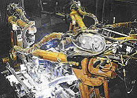
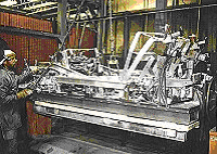
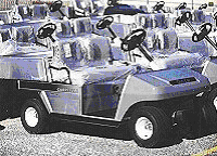
In the nineteen nineties, I set the first "multi-robot robot cell line" utilized in North America to weld a large volume, large aluminum frame fabrications. Take a look at the above photos of ABB robots welding the aluminum golf cart frames.
Note: These robot aluminum MIG welds were made about 25 years ago and were made without push-pull guns.
ROBOTS AND ALUMINUM MIG WELDS.
In the nineteen nineties, I set the first "multi-robot robot cell line" utilized in North America to weld a large volume, large aluminum frame fabrications. Take a look at the above photos of ABB robots welding the aluminum golf cart frames.
Note: These robot aluminum MIG welds made about 25 years ago were made without the need for push-pull guns.
So what's so difficult about MIG welding an aluminum golf cart frames using multi-robots in a single robot weld cell? The first thing to be aware of this was in the days when pulsed MIG equipment weld performance was poor and erratic.
Think of all the aluminum MIG weld issues that the robot technicians will have to deal with in a robot cell that has four robots at the same time welding on an aluminum gauge application that required numerous welds.
[] The robot technicians would experience wire feedability issues.
[] The robot technicians will have to deal with the common aluminum MIG wire burn back issues. [] The robot will have to deal with the common weld joint alignment and weld gap deviations, that results from the mfg, engineers not doing their jobs.
Note: MIG welding gaps is rarely an issue with steels, its a bigger problem with aluminum.
[] The robot technicians will have to be aware that on alum, applications, the aluminum parts will heat up rapidly which can add to increased weld fluidity and weld burn through potential.
[] The robot technicians will have to deal with weld fusion and porosity concerns.
[] The robot technicians will also become an expert in dealing with weld craters and ensure no weld cracking is taking place.
Many things will go wrong in aluminum robot MIG weld cells, and especially with multi-robots welding the same part. Please rember that once one robot is down as a result of a weld issue, while the robot technician is fixing the issue, the other robots sit dormant while the production manager screams and reaches for his packet of TUMS.
2018. Approx. two decades have passed since I set the ABB robot MIG welds on the aluminum Club Car golf carts. And in this time period, in contrast to more than 80% of the arc welding robot being utilized in the auto-truck industry that are welding simple "carbon steel" parts, the four robots I set welding the aluminum frames have achieved much greater robot weld production efficiency, with superior weld quality and less weld rework. And what was the magic that I practiced twenty five years ago to create this sucessfull applications. I used my weld process controls - best weld practice expertise. This expertise which I upgrade every year in the programs, is found in my low cost MIG weld process controls - best weld practice, self teaching and training resources.
From welding golf carts to ships, or welds on aerospace and defense applications, my self teaching / training MIG - Flux Cored - Advanced TIG and TIP TIG, Weld Process Controls and Best Weld Practice programs are your keys to all sucessful weld applications.MIG - Flux Cored - Advanced TIG or TIP TIG welds.
I set the above aluminum Club Car golf cart frames and later on when as the ship yard manager I was reducing the ship building flux cored weld rework by more than 70% at Aker Ship Yard, Philadelphia, I used to drive around on a Club Car golf cart knowing that both the ships and vehicle had the best possible aluminum weld quality.
THE 1990's WAS A SAD TIME FOR ELECTRONICS AND PULSED MIG EQUIPMENT.
A PRIME ISSUE WITH THE COMPLEX, ROBOT, ALUMINUM, GOLF CART APPLICATION WAS THAT PUSH PULL GUNS WERE NOT ALLOWED FOR THE SOFT WIRES UTILIZED AND THEREFORE BOTH ALUMINUM WIRE FEED ISSUES AND WIRE BURN BACKS TO THE CONTACT TIPS WERE A MAJOR CONCERN:
TO GET THEIR ROBOT LINE CONTRACT, CLUB CAR REQUIRED THAT ANY ROBOT COMPANY THAT WANTED TO BID ON THE COSTLY ROBOT WELDING LINE, PERFORM A WELD TEST THAT REQUIRED A ROBOT COULD PROVIDE AT LEAST 10,000 ARC STARTS ON ALUMINUM SHEET METAL AND NOT ALLOW MORE THAN 10 WIRE BURN BACKS OR 10 WIRE FEED ISSUES WITH THE 0.046 (1.2 mm) ALUMINUM WIRE.
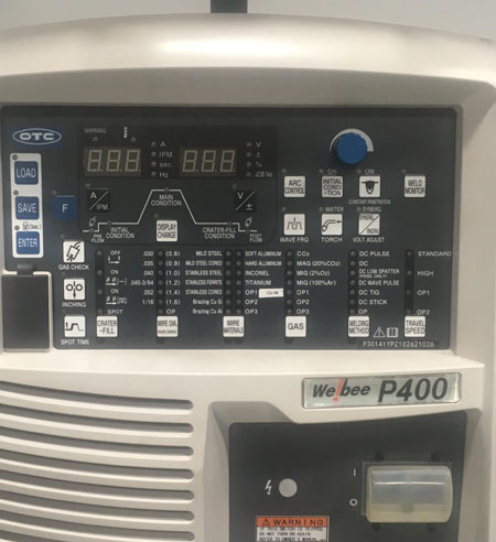
FOR THE ALUM WELDS I FIRST ESTABLISHED THE OTIMUM ALUMINUM WELD PARAMETERS FOR THE ROBOT ARC STARTS AND ALSO SELECTED THE BEST WELD CONSUMABLES. I COMPLETED THE ROBOT MIG ALUMINUM ARC START WELD TEST WITH 7000 ARC STARTS WITHOUT A SINGLE ALUMINUM WIRE BURN BACK. REMEMBER THIS WAS QUITE A FEAT IN THE 1990s, AND ABB GOT THE ROBOT CONTRACT..FOR THE THIN ALUMINUM CLUB CAR FRAME WELDS, I SELECTED THE BEST PULSED MIG EQUIPMENT AVAILABLE IN THE 1990s, THIS WAS AS IT IS TODAY IN 2019, AN OTC DAIHEN PULSED MIG UNIT.
OTC PULSED MIG EQUIPMENT WAS TESTED BY EM OVER A 15 YEAR PERIOD.
For more than two decades, OTC has made the best pulsed MIG equipment.
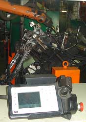
ED AND THE HIGHLY QUALIFIED ABB ROBOT PROGRAMMING TEAM AT ABB FORT COLLINS CO, USED ABB ROBOTS, A TRADITIONAL MIG GUN (NO PUSH PULL), AN OTC POWER SOURCE, AN ALCO TECH WIRE FEED DE-REELER, HARD PLASTIC LINERS. AND OF COURSE ED USED HIS WELD BEST PRACTICE - PROCESS CONTROL EXPERTISE TO SET THE ROBOT MIG WELD PROGRAMS.
Note: Ed at that time was the North American Weld Manager for ABB Robotics Division.
Weld production efficiency is greatly influenced
when you have the robots working together without down time.
A problem with multi-robot weld cells, when 1 robot has an issue,
the others will be having a break.
1990s: MORE ON THE ALUMINUM GOLF CART FRAMES:
2019 ALUMINUM WELDING CONCERNS AND EXCELLANT ROBOT PROGRAMMING FROM 20 YEARS AGO:
WITH THE MULTI-ROBOTS IN A SINGLE CELL WELDING THIN ALUMINUM. NO PUSH PULL GUNS WERE ALLOWED FOR THE SMALL ALUMINUM 0.046 WIRES AND OF COURSE WIRE FEED AND BURNBACK ISSUES WERE TO BE AVOIDED. GOLF CARTS OR AUTOMOTIVE PARTS, MUST ALL EMPLOY THE SAME MECHANICAL ENGINEERS AS POOR WELD JOINT FIT AND OVERSIZED WELD GAPS WAS AS USUAL THE NORM. TYPICAL WELD HEAT BUILDUP CONCERNS WERE GENERSTED WHICH WITH THE ALUMINUM FRAME AND THIS INCREASED THE WELD BURNTHROUGH POTENTIAL. POROSITY, CRATER AND CRACKING CONCERNS WERE TO BE MININMIZED.ROBOT FEATURES THAT ENHANCED THE ALUMINUM WELDS.
When this robot aluminum Club Car job started, I had to establish the MIG robot aluminum welds to compensate for the aluminum gage weld heat build up, the frame part fit issues and and the weld gaps. Each of the four ABB robots produced approx. 30 to 50 welds per-frame.* ABB provided the best possible Automatic Torch Alignment system, (Tool Center Point). The ABB system can make 3-D and angular calculation via it's patented BullsEye Automatic TCP calibration system. The Bulls Eye automatically adjusts the Tool Center Point program for the MIG guns, eliminating the need for gun touch ups and minimizing weld rework and down time* The ABB cell also provided automatic Error Handling Capability. This is a necessary feature when robots are in close proximity and the robots had to complete > 130 welds on each frame, (stoppe robots beating each other up in possible robot collisions).
* ABB used robot I/O between all four robots. If one robot had an error, it communicated the error the other three. The other robots would then finish the weld they are doing, but would not move to the next weld until they receive a "Clear to Go" signal. In the meantime, the robot with the error automatically goes to a service position where an operator can quickly check the problem.
* The robots used regular MIG guns with "super rigid plastic liners. It took me awhile to find a liner that was rigid enough..
* To reduce the soft aluminum wire feed issues which would have influenced wire feed burn backs at the weld starts and in the welds I utilized Alco Tech Alum Wire Dee-Reelers and off course no Chinease consumables was going in this cell so I selected American made Alco aluminum wire.
DO YOU HAVE THE EXPERTISE TO ENABLE HAPPY ROBOTS, PRODUCING, OPTIMUM MIG WELD QUALITY, WITH MINIMUM ROBOT DOWN TIME AND MAXIMUM WELD PRODUCTION?
IT WAS MORE ABOUT MIG PROCESS CONTROL
EXPERTISE THAN IT WAS ABOUT THE EQUIPMENT.
I think my above aluminum robot MIG production began production around 1998. Since that time, the golf cart company has likely produced well over 200,000 aluminum golf cart frames. Two people operate the system, one loads a fixture in one cell, while the robots are welding in the other cell. I believe (not sure) that the robot arc on time for the 130 welds on the Club Car frames was approx. 6 minutes as compared with 27 to 30 minutes that manual MIG welders would require to weld the aluminum frames. Over the last 50 years. my achievements around the globe on numrous difficult applications sich as this weld came from my process controls - best practice expertise. By the way this expertise was missing in the 1980s, and its still missing in 2018.
MANAGERS AND ENGINEERS WOULD BE FOOLISH AND POSSIBLY IN THE WRONG CAREERS, IF THEY DON'T LOOK BACK AT WELD APPLICATIONS AND WHAT WORKED: Ed Craig 1989.
ABB and the pathetic ESAB Arcitec Pulsed Weld Issues on FORD parts.
During 2000, I was requested by a manager at VAW a tier one supplier to analyze the weld performance of their new ABB robot and ESAB Swedish Arcitec welding equipment. The VAW plant produces extruded aluminum parts. The aluminum parts were made into car seats for Ford.
The car seats required many small robot welds produced on thin gage 6061 aluminum.
Since the installation of the new ABB robot cells at VAW, continuous, consistent production and optimum weld had not been attained due to the management induced issues documented in this aluminum weld story. The weld reject rates averaged sixty percent and the robot down time per hour averaged 20 to 30 minutes per-robot. This is the rest of the Alum Welding Story.
ABB and ESAB screwed up the Robot MIG Welds on
the Ford, 6061 Aluminum Car Seats.
ESAB and ABB, two Swedes at this time should
have stayed away from each other.
During 2000, I was requested by an engineer at VAW, a tier one supplier to analyze the welding performance of their ABB robot and ESAB Arcitec welding equipment. This plant produces extruded aluminum parts. The aluminum welded car seats were for Ford. The car seats and parts required small welds which were made on thin gage 6061 aluminum.
Criterion Machinery was the system integrator for the seat frame parts. Two ABB robot cells were ordered, ABB advised Criterion that their "Swedish Arcitec" welding power source could handle the thin gage aluminum welding requirements.
The ABB sales induced Arcitec power source claim to fame was, it was unique in that it was one of the first MIG power sources that was truly integrated into an ABB robot control panel.Two ABB robot cells containing the Arcitec power sources were shipped to Criterion for initial fixture and weld tests. The weld tests carried out at this time were minimal as Criterion and VAW did not have the necessary weld process expertise to evaluate the Arcitec or for that matter any MIG power source.
Since the installation of the robot cells at VAW, continuous production of optimum weld quality parts has been impossible. Weld reject rates averaged sixty percent and each robot down time per hour averaged 20 to 30 minutes.
Many issues are documented and I have not included them all here, however the primary cause of the extensive weld quality and productivity issues at VAW was the ABB Arcitec pulsed power source .
This MIG weld equipment was poorly designed by ESAB and had extensive electronic problems. The bottom line with this power source was when the best possible weld parameters were set, the weld results were always inconsistent and especially unsuited to the needs for the high volume, small welds on the thin aluminum Ford seats.Arcitec Power source History.
The Arcitec power source was manufactured by ESAB in Sweden in the late 1990s. The Arcitec was an inverter pulsed GMAW power source. This power source was integrated into the ABB S4/S4C robot controls in an attempt to improve the communication "response time" between the robot controller and welding power source.
Note: Before this time all MIG power sources were seperated from the robots and the power source controls were typically sold by the MIG equipment mfg.
I had extensive knowledge of Arcitec MIG power source issues, as I was prevdiously employed by ABB, a Swedish manufacturer of robots. My position with ABB was weld manager / Senior weld process engineer. Part of my responsibility was to evaluate the application performance of any welding equipment and this included the ESAB Arcitec unit.
I have evaluated numerous MIG power sources over at least four decades and cannot recall any MIG welding power source that even came close to the amount of welding issues generated by the ESAB Arcitec. The bottom line, this equipment was introduced by ESAB to ABB and the USA market place without sufficient testing by ESAB.
The German Marketing Manager at ABB Fort Collins, made the mistake of believing the Swedish sales BS from the weld equipment product marketing manager at ESAB in Sweden. And when you get two marketing people making weld decisions, well you know you are likely to need a shovel fot the BS thats going to be deliverd.
Over 100 units were ordered from ESAB by ABB to be installed in the ABB robots for North America.
When I got my hands on the Arcitec I put it through weld test capability and it took less than one hour to reveal the erratic weld performance and many other issues. I documented the Arcitec faults and the demonstrated the issues to the ABB marketing manager. However as this manager had already foolishly ordered more than one million dollars worth of Arcitec inventory, he was not happy with my weld reality and he ignored the Arcitec test results and my reports.
As a result of the never ending software / hardware issues and erratic performance from the ESAB Arcitec, eventually ABB did reduce it's focus and promotion of the European ESAB package and instead focused on promoting either the slightly less inconsistent Miller Invision, and the lets create a weld problem Lincoln Power Wave.
Car seat tube welds are simple if you
understand the MIG weld modes,Four years after the introduction of the erratic Arcitec, I was requested by VAW to evaluate their poor performing robot installations. I knew the installation had an Arcitech power source, however I was under the impression that the poor performing Arcitecs were taken out of service and I would be examining new ESAB units that had evolved electronically from the original equipment I had evaluated four years previously. What I saw while welding at VAW was I believe the same Arcitech power sources which were manufactured four years earlier. The units I tested at VAW certainly had the same unique electronic glitches causing burn backs and other issues which I was familiar with, and the power sources still produced an inconsistent output weld voltage and weld performance.
VAW and it's Arcitec experiences:
[] A few months after VAW accepted the robot cells, "three Arcitec power sources were replaced" by ABB. The typical life of a traditional MIG power source is 10 years without requiring repairs. With the more sophisticated, inverter pulsed equipment one would anticipate that this equipment should at least last till the warranty runs out, which is typically one to three years.
[] Five months after the robots were installed, the two robots with replaced Arcitech equipment were unable to produce consistent, acceptable weld production or quality. Weld reject rates were in the 60-70%% range and the production cycle efficiency rarely attained 40%.
[]A Primary Weld Issue. "Wire Burn Backs"
From a weld production perspective a serious issue was the numerous welding wire burn backs that were generated during the arc starts requiring tip changes.
As you see in this one application the issues that are generated with process ignorance and lack of process ownership. VAW was within a few days of loosing the Ford contract, I had three days to fix the problems before the full production requirements for Ford. I solved the problem, if you want to know how, look me up and I will tell you the rest of the story.
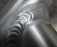
This is what I call a really GOOD production aluminum weld?
Why. The weld energy - profile and fusion line continuity and
weld surface indicate an optimum Alum Weld.
My optimum aluminum MIG weld is shown in above picture. Note the fluid weld energy, the resulting weld freeze lines, the weld uniformity, lack of scalloped weld edges and good start / stop results.In contrast, as indicated below, many weld shops that produce aluminum welds promote the myth that a good alum weld will show with MIG welds, the pulse fast freeze effects or the TIG intermittent wire feed which produces a similar effect. These colder alum welds will create scalloped weld edges, and if a macro is taken, it will in contrast to the weld above, reveal either lack of fusion or inconsistent weld fusion. Also remember that the faster the alum weld freezes the greater the potential for weld porosity.
Sad but common pulsed MIG alum. weld.
Pulsed freeze lines may look neat on an alum. bike welded with a high energy slow TIG weld, however be aware that the lower energy, faster pulsed MIG weld speeds like this will likely have weld weld fusion concerns.
There are more than 400 wrought aluminum alloys, and over 200 aluminum alloys in the forms of castings and ignots registered with the Aluminum Association.
Wrought Aluminum Alloy Designations have 4 digits.
Aluminum is alloyed with a number of elements necessary to provide improved weldability, strength and corrosion resistance.
The primary elements that alloy with aluminum are;
[] copper,
[] silicon,
[] manganese,
[] magnesium,
[] zinc.
Aluminum Alloy Information
First digit is principle aluminum alloy. First digit also describes the aluminum series. Ksi is ultimate tensile strength range.1XXX
> 99% Aluminum
non heat treatable
10-27 ksi
2XXX
Alu - Copper approx.
2 - 10% provides strength and allows precipitation hardening. Watch for weld solidification crackingheat treatable
27-62 ksi
3XXXAlu-Manganese. Provides increased strength
non heat treatable
16-41 ksi
4XXX
Alu-Silicon. Reduces melting temperature, welds more fluid. When combined with magnesium provides an alloy that can be heat treated.
Both heat treatable and none heat treatable
25-55 ksi
5XXXAlu - Magnesium. Increases strength
none heat treatable
18-51 ksi
6XXX
Alu Magnesium and Silicon
Creates a unique compound magnesium silicide Mg2Si. Allows special heat treat properties, suitable for extrusion componentsheat treatable
18 - 58 ksi
7XXX
Alu- Zinc. When you add zinc copper and magnesium you get a heat treatable alum alloy of very high strength. Watch for stress corrosion cracking. Some alloys MIG weldable some not
heat treatable
32 -88 ksi
None Heat Treatable Aluminum Alloys.
With these alloys it's possible to increase the alum strength through cold working or strain hardening. To attain the desired strength, a mechanical deformation must first occur in the aluminum structure, the deformation will result in increased resistance to strain producing both higher strength and lower ductility.
These alloys are different from "heat-treatable alloys" as the non-heat treatable alloys cannot form second-phase precipitates for improved strength. Non-heat-treatable alloys cannot achieve the high strengths characteristics of heat treatable precipitation-hardened alloys.
The absence of precipitate-forming elements in the low- to moderate-strength, non-heat-treatable alloys is beneficial from a welding perspective as many of the alloy additions needed for HEAT TREATABLE precipitation hardening, copper plus magnesium, or magnesium plus silicon can lead to hot cracking during welding. The heat affected zone (HAZ) mechanical properties are higher in not-heat treatable alloys as the HAZ is not compromised by coarsening or dissolution of precipitates.
Non Heat Treatable wrought aluminum alloys can be placed into one of four groups,
1xxx Al (Al 99% minimum purity)
3xxx Al + Mn
4xxx Al + Si (some exceptions)
5xxx Al + MgFiller alloys used to join Non-Heat-Treatable alloys typically come from three alloy groups:
1xxx
4xxx
5xxxCommonly used filler alloys for None Heat Treatable alloys include,
1100, 1188,
4043, 4047,
5554, 5654, 5183, 5356, 5556.
When MIG or TIG welding Non-Heat Treatable aluminum alloys, note that the HAZ will be annealed during the weld. The none heat treatable alloys are annealed during welding in the 600-700 F, range, the time required at this temperature is short. The alum welds will have minimal impact on the transverse ultimate tensile strength of a groove weld as the annealed HAZ of the none heat treatable alum alloys will usually be the weakest area of the weld joint.
Weld procedure qualification for the None-Heat Treat alloys is typically based on the minimum tensile strength of the alum base alloy in its annealed condition.
When welding the Non-Heat-Treatable alloys microstructure damage will occur in the HAZ. The HAZ damage in non-heat-treatable alloys is however minimal effecting both recrystallization / grain growth. In contrast with the heat treatable alloys the mechanical properties loss is extensive.Note: When welding all aluminum alloys, please note: To help retain the properties in the Aluminum HAZ locations, always use low to conservative TIG or MIG weld parameters, think low weld heat. Low weld heat is one of the great real world benefits of using the pulsed MIG weld transfer mode on aluminum applications.
For the None Heat Treatable series that require strength, the 5xxx- alloys are popular for applications where good joint strengths can be obtained in the as-welded condition without the need for post-weld heat treatment.
The 1xxx, 3xxx, and 5xxx series wrought aluminum alloys are Non-Heat Treatable and are strain hardenable only.
The Heat Treatable alumumin alloys when welded will attain their optimum mechanical properties through controlled post heat treatment.
The 2xxx, 6xxx, and 7xxx series wrought aluminum alloys are Heat Treatable. In contrast the 4xxx series consist of both heat treatable and non-heat treatable alloys, beware of hot cracking with some of these alloys.
Remember before welding that the Heat Treatable alloys will typically have attained their mechanical properties through Solution Heat Treatment and Artificial Aging.
Solution Heat Treatment is the process of heating to temperatures (around 990 Deg. F). In this temperature range the alloying elements or compounds go into solution. After heating the part is quenched typically in in water. The quench produces a supersaturated solution at room temperature. Solution heat treatment is usually followed by Aging to attain required properties.
Aging. The precipitation of a portion of the elements or compounds from a supersaturated solution in order to yield the required properties.Heat treatable aluminum alloys after welding.The Heat Treatable alloys go through "Post Heat Treatment" after welding to regain the strength lost during the welding process. When post heat-treat is applied to these alloys;
[1] Step 1, the post heat must place the alloy elements into solid solution.
[2] Step 2, provide controlled cooling after the heat treatment, this will produce a supersaturated solution. [3} Step 3 is final step in the post weld heat treat process. Maintain the welded part at a low temperature and the time required has to be long enough to allow a controlled amount of precipitation of the aluminum alloying elements.The affect of a weld on a heat treated alum alloy HAZ is partially annealed and overaged, remember the higher the weld joules (volts - amps- travel speed) with heat treatable alloys, the lower the as welded strength of HAZ locations.
Note: With heat treatable or none heat treatable aluminum alloys, the differences between the
MIG and TIG heat affected weld zones (HAZ) and the base metal affected by the weld heat can be significant.
With none heat treatable aluminum alloys in the 1xxx - 3xxx - 4xxx - 5xxx series, the reduction of the HAZ tensile strength is typically predictable under normal weld conditions. In contrast the HAZ area strength with heat treatable alloys 2xxx - 6xxx - 7xxx can be reduced below the minimum tensile strength required for the parts when the welding heat is excessive during the weld. Higher tensile strength from the filler and reduced strength from the part influenced by the annealing effect of the weld and you have hot cracking in the HAZ of the base metal.
Alum Designations. Aluminum alloys can be classified by a temper designation.
O = Annealed,
T = Thermally treated,
F = As fabricated,
H = Strain hardened;
W = Solution heat-treated which can designated both heat treatment, or cold working aging.Wrought aluminum alloys are alloys that are rolled from ingot or extruded. Alloys can also be divided into a cast group of alloys. Cast alloys are those used to manufacture parts from molten alloys of aluminum poured into molds. Cast alloys are precipitation hardenable but never strain hardenable. The weldability of cast alloys is affected by casting type - permanent mold, die cast, and sand. A three-digit number, plus one decimal i.e. 2xxx designates the copper cast alloys.
There is a place for the Rapid Freeze distinct slow pulse alum. weld.
Some times with "thin" aluminum parts, you need to see the rapid freeze lines and scalloped weld edges that are necessary to avoid weld burn through as indicated above. As the above aluminm box welds are out side, gage corner welds, the number one issue would be weld burnthrough. These welds benefit from the Pulsed MIG modes in which the pulsed rate is adjusted so the weld drops cause rapid freeze welds with distinct paterns as provided above.
Note: With manual TIG, the welder dipping their wire in and out of the weld pool creates the same rapid weld freeze effect. Remember the rapid freeze weld appearence while fine on a thin bike frames may indicate lack of weld fusion or excess porosity when the alum parts > 3 mm.
Important, on aluminum parts > 4mm, you wil get better weld fusion results if your welds provide higher energy, more rapid weld transfer, (like MIG Spray welds). Weld below is an an optimum aluminum weld.
Remember the purpose of any weld.
When the aluminum parts can take the weld heat,
those alum MIG welds should look similar to a MIG Steel Spray weld.
Cast Aluminum Alloy Designations:
Aluminum Casts have three digits and one decimal place (XXX.X).
XXX .X (.X - .O = casting - .1 or .2 = ingot)... If a capital letter precedes the numbers this is a modified version.
1XXX
99% Min Alum 2XXX
Copper 3XXX
Silicon + Cu and or magnesium 4XXX
Silicon 5XXX
Magnesium 6XXX
Unused Series 7XXX
Zinc 8XXX
Tin 9XXX
Other Elements Weldable grades of Aluminum Castings are
319.0, 355.0, 356.0, 443.0, 444.0, 520.0, 535.0, 710.0 and 712.0.
Aluminum Physical Properties. Lets look at how Aluminum compares to Steels.
[] The typical weld characteristics of steel or stainless don't apply when MIG or TIG welding aluminum.
[] Aluminum has higher thermal conductivity and lower melting temperatures, both factors will influence weld solidification, weld burn through potential, stresses, HAZ strength and distortion.[] Aluminum is three times lighter than steel and yet can offer high strength when alloyed with the right elements.
[] Aluminum can conduct electricity six times better than steel and nearly 30 times better than stainless steel.
[] Aluminum provides excellent corrosion resistance.
[] Aluminum is easy to cut and form.
[] Aluminum is nontoxic for food applications.
[] Aluminum is non-magnetic therefore arc blow is not a problem during welding.
[] Aluminum has a thermal conductivity rate five times higher than steel. The high thermal conductivity creates a great heat sink which can create insufficient weld fusion on parts over 4 mm and weld burn through issues on parts less than 3 mm. The weld fusion concerns is one reason to consider the MIG Spray transfer mode instead of pulsed MIG on specific alum applications especially > 4 mm.
[] Aluminum provides welds that are less less viscous which is a problem when trying to get weld fusion with the MIG short circuit mode. Pulsed MIG improves the weld viscosity on all thin aluminum applications and the the viscosity can be furher improved when using MIG Spray for all position alum. welds.
[] Aluminum has a low melting point 1,200F which is more than half that of steel. For a given MIG wire diameter the Transition Short to Spray weld current for aluminum is much lower than required for steels.
Aluminum Descriptions.
1XXX. Minimum 99% aluminum. This very low strength series is considered none-heat treatable and is used primarily for bus bars and some pipe and chemical tanks. This alloy provides superior corrosion resistance. Alloys with purity levels greater than 99,5% are used for electrical conductors (for example alloy 1350). 1XXX series are easily welded with 1100 and 4043 alloys.
2XXX. Alu-Copper provides approx. 2 to 6% Cu with small amounts of other elements. The Cu increases strength and enables precipitation hardening. The 2XXX series is mainly used in the aerospace industry. Most of the 2XXX alloys have poor weldability due to their sensitivity to hot cracking. These alloys are generally welded with 4043 or 4145 series filler electrodes. These filler metals have low melting points which help reduce the probability of hot cracking. Exceptions to this are alloys 2014, 2219 and 2519, which are readily welded with 2319 filler wires. Hot cracking sensitivity in these Al-Cu alloys increases as copper is added up to 3% and decreases when the copper is above 4.5% Be wary of Alloy 2024 as it is crack sensitive.
3XXX. Alu-Manganese when added to aluminum produces a moderate strength, none-heat treatable series typically used for radiators, cooking pans, air conditioning components and beverage containers and storage equipment. The 3XXX series is improved through strain hardening which provides improved corrosion properties and improved ductility. Typically welded with 4043 or 5356 electrode, the 3XXX series is excellent for welding and not prone to hot cracking. The moderate strength of this series prevent these alloys from being utilized in specific fabrication or structural applications.
4XXX. Alu-Silicon reduces melting temperature improves fluidity. The most common use is as a welding filler material. The 4xxx-series alloys have limited industrial application in wrought form. If magnesium added it produces a precipitation hardening, heat treatable alloy. The 4XXX series has good weldability and can be a non-heat-treatable and heat treatable alloy. Used for castings, weld wires. The 4xxx wires are more difficult to feed than the 5xxx series.
5XXX. Alu-Magnesium increases mechanical properties through solid solution strengthening and improves strain hardening potential. These alloys have excellent weldability with a minimal loss of strength. The 5XXX series has lower tendency for Hot Cracking. The 5XXX series provides the highest strength of the nonheat-treatable aluminum alloys. These alloys are used for Cryo-vessels, chemical storage tanks, auto parts, pressure vessels at elevated temperatures, as well as structural applications, railway cars, trailers, dump trucks and bridges because of the corrosion resistance.
Note: 5xxx looses ductility when welded with 4xxx series fillers due to formation of Mg2Si.
5xxx Series & Weld Crack Sensitivity: The 5XXX typically while welding with or without filler metal have low crack sensitivity. Usually the filler metal will have a little more Mg than the base metals being welded. Be wary of welding 5052, especially if TIG welding without a filler metal. Use a high Mg filler like 5356 for the 5052 alloy. All aluminum concave fillet welds and concave craters are sensitive to hot cracks.
6XXX. Alu-Magnesium & Silicon combined magnesium-silicides and serve as alloying elements for this medium-strength, heat-treatable series. 6XXX are principally used in automotive, pipe, structural, railings and extruded parts. This series can be prone to hot cracking, but this problem can be overcome by the correct choice of joint and filler metal and weld procedures that minimize weld heat input. These alloys can be welded with either 5XXX or 4XXX series weld wires. Note that adequate dilution of the base alloys with selected filler alloy is essential. 4043 electrode is the most common filler metal for this series. Be wary of liquation cracking in the HAZ when using specific 5xxx alloys. See Liquation cracking above notes.
Note: 6xxx & Crack Sensitivity: As many of the 6xxx alloys have 1.0% magnesium silicide, these alloys are crack sensitive. Avoid welding without filler metal and do not use a 6xxx material as a filler metal. Using 4xxx or 5xxx filler metals reduces crack sensitivity as long as sufficient weld metal is added and good weld dilution occurs with the 6xxx base metals. Avoid weld joints in which minimal weld dilution occurs, a vee prep is superior to a square groove. All 6xxx aluminum applications that have concave welds and concave craters are sensitive to hot cracks.
7XXX. Alu-Zinc...When added to aluminum the magnesium and copper permits precipitation hardening and produces the highest strength heat-treatable aluminum alloy. These alloys are primarily used in the aircraft industry, armored vehicles and bike frames. The weldability of the 7XXX series is compromised in higher copper grades, as many of these grades are crack sensitive (due to wide melting ranges and low solidus melting temperatures.), also susceptible to stress corrosion cracking. Grades 7005 and 7039 are weldable with 5XXX fillers.
7xxx Crack Sensitivity:The 7xxx Al-Zn-Mg alloys are typically welded with 5356, avoid 4043. These alloys resist hot cracking better than the 7xxx Al-Zn-Mg-Cu alloys.
8XXX. Other elements that are alloyed with aluminum (i.e. Lithium) all fall under this series. Most of these alloys are not commonly welded, though they offer very good rigidity and are principally used in the aerospace industry. Filler metal selection for these heat-treatable alloys include the 4XXX series.
Freeze lines do not promote consistent weld fusion and minimum porosity.
Again the above alum welds look neat and many alum welders like this look, however it does not matter if its a MIG steel or aluminum weld, with welds that have freeze lines like this, the weld fusion is questionable and weld porosity potential is increased especially on aluminum parts that are > 4 mm thick.
Panasonic Weld Equipment Issues, and lack of aluminum weld process expertise:
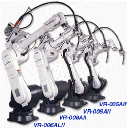
The company I visited was welding 6xxx series, extruded aluminum, thin gage parts. They had purchased a Panasonic VR OOGAL 11robot, with a Panasonic 350 amp Panastar RA 350 pulsed power source. For the welds they used an 0.046, 4043 wire and argon. The MIG wire spool was mounted on top of the robot, and they used a regular four-drive roll feeder with a water-cooled gun.
The problem robot welds were short lengths, 5/8 to ¾ long (5 to 18 mm) . The robot welds were made on aluminum square tubes 0.070 thick. The 6xxx tubes are welded to a thicker alum part 3/16 thick. Since they purchased the robot the completed welds never look consistent over their short lengths. All the thin tube welds were made with the same weld data, yet in the same locations on different parts, some welds look very fluid while other welds look very cold. Most of the welds ended up with a black and dirty appearance yet the push gun angle were correct. These welds caused so many issues the company was ready to give up the robot and go back to manual TIG. For the rest of the story, click here.
ITS THE THIN PARTS THAT BENEFIT FROM CONSISTENT PULSED TIG WELDS LIKE THIS BEAUTY,
Optimum balanced wave TIG weld made above on thin alum part. Rememeber with aluminum we have one set of weld concerns with parts < 3 mm (burnthrough) and on parts > 4 mm we have weld fusion and porosity concerns that are reduced with higher energy welds..
Aluminum Weld Tips and Information:
Aluminum alloys provide unique physical properties.
Weight. Aluminum is three times lighter than steel and yet aluminum can provide higher strength when alloyed with specific elements.
None Magnetic. Since aluminum is nonmagnetic, arc blow is not a problem during aluminum welding.
Thermal Conductivity. With a thermal conductivity rate that is five to six times higher than steel and the aluminum welds watch out for lack of weld fusion especially at the weld starts. With alum being more sluggish and less fluid, aluminum can be welded in all positions with spray and pulsed with relative ease. In contrast to steel the high conductivity of aluminum acts as a heat sink making weld fusion and weld penetration more difficult to achieve on parts > 4 mm.. However on thin parts, the rapid build up of heat in the alum parts can add to high weld fluidity and weld burn through potential.
As most alum. welds are weaker than steels, of course weld porosity will be a concern.
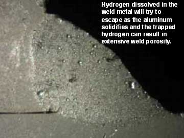
Aluminum Porosity and Hydrogen. When MIG or TIG welding aluminum, the weld decision maker should always be aware that this is one of the metals that are most susceptible to porosity. The main cause of porosity in aluminum welds is the absorption of hydrogen in the weld pool which forms gas pores in the solidifying weld metal. The most common sources of hydrogen are hydrocarbons and moisture from contaminants on the aluminum base metal and on the filler wire surface. Also water vapor from the MIG or TIG shielding gas will provide the same results.
The trapped hydrogen can result in extensive weld porosity which can often be extensive
Note: Hydrogen cracking is common with low alloy carbon steels but hydrogen cracking will not occur with aluminum. Hot cracking or solidification cracking is a primary cause for aluminum cracks.
Aluminum solidification cracks.
As we are all aware aluminum is much weaker than steel and has a much lower weld solidification temperature. These cracks typically occur due to thermal expansion and contraction. The resulting stresses may tear the weld apart..
Common causes of alum solidification cracks.
[a] incorrect choice of alum weld consumable.
[b] Concave welds, undersize welds, and welds with insufficient weld throat. (The weld throat depth must be sufficient to compensate for the weld contraction stresses).
[c] Weld joints too rigid.
[d] Poor weld weld geometry.
[e] Poor weld joint design. Weld restraint and weld stresses can be reduced by focussing on the weld edge prep, the weld sequence.
[f] Excess weld heat, watch weld pass sequence and on multi-pass welds consider interpass temperature control.
Note: Solidification cracking is reduced with the selection of crack-resistant filler metal like the 4xxx and 5xxx filler metal. Be wary when choosing the filler metal to specifically reduce weld cracking, as the weld metal may provide lower strength than the parent metal and will notrespond to heat treatment if applied.
Aluminum and Liquation Cracking. In contrast to hot cracking which occurs in the weld, with MIG or TIG welds on aluminum liquation cracking will occur in the welds's heat affected zone (HAZ).
With liquation cracking low melting point films are formed at the grain boundaries and these films (liquid elements) cannot withstand the contraction stresses during the weld metal solidification. Heat treatable alloys, like the 6xxx and 7xxx series are sensitive to liquation cracking. To reduce the potential for liquation cracking, consider a weld wire with a lower melt temperature than the parent metal. With alloy 6061 - 6082, liquation cracking can occur in the partially melted zone when a weld with good dilution is made with 5356 or similar filler metal is utilized. In contrast when welding the same alloys with 4043 liquation cracking should not occur.
In contrast to most car and truck plants in which lack of MIG weld process controls
expertise is the NORM, how would you define a quality weld?
The influence of the Aluminum Oxide Layer. Aluminum combines with oxygen to form an aluminum oxide layer on it'd surface. This layer will form instantly as the aluminum surface is damaged. The aluminum oxide layer is so thin its difficult to measure. This layer can also be very porous.
[] The aluminum oxide layer can act like a sponge and readily trap moisture, oil, grease and other materials. This entrapment can add to the potential for hydrogen pickup.
[] The aluminum oxide layer provides excellent corrosion resistance, however this is a layer that must be removed for optimum weld quality.
[] Due to the oxide layer higher melting point, approx. 3700F, the oxide layer if not removed can decrease the weld fusion. [] The oxide layer is removed during the weld with the fore hand (push) technique. During forehand weld travel, the gas molecules in the arc plasma collide with the oxide surface moving the oxides.
[] The oxides are also disrupted through mechanical cleaning, wire brushing, solvents and chemical etching however they almost instantly renew.
[] MIG weld voltage control (arc length) also influences the oxide removal. One of the best practices to attain clean alum MIG welds is to "use the lowest possible open arc pulsed or spray voltage". The low voltage assures a short arc length, that results in a concentrated arc plasma which assists in the oxide removal.
Aluminum alloys that are difficult to weld or sensitive to cracking.Alloys that may be sensitive to hot cracking are found in the 2xxx series, alum-copper, and in the 7xxx series, alum-zinc.
With the 2xxx series hot cracking sensitivity increases with Cu < 3% and decreases with Cu > 4.5%. Avoid weld practices that promote high heat input as grain boundary segregation cracking potential.7xxx alloys that contain Al-Zn-Mg like 7005 resist hot cracking and have better mechanical weld properties than Al-Zn-Mg-Cu alloys like 7075 that contain small amounts of Mg and Cu which extend the coherance range increasing the crack sensitivity. Zirconium is added to refine grain size and reduce crack potential. Electrode 5356 is often recommended for this group as the magnesium helps prevent cracking. The 4043 electrode would provide excess Si promoting brittle Mg2Si particles in the welds.
Be careful when welding dissimilar alum alloys as extending the coherence range increases the crack sensitivity. When welding alloys that do have good weldability like welding a 5xxx alloy to a 2xxx base alloy or a 2xxx filler on a 5xxx alloy and vice a versa you can end up with high Mg and Cu and increase the coherence range increasing the crack sensitivity.
5356 - 4043 - 1100 - 5556 - 4047Usually the filler metal selected should be similar in composition to the base metal alloy for example a 1XXX filler wire for welding 1XXX - 3XXX-series base metal alloys. Special consideration is however required when weldability is an issue. Weldability of non-heat-treatable aluminum alloys should be measured in resistance to hot cracking and porosity potential. Hot cracking issues are encountered when welding with alloys sensitive to cracking, alloys subject to excess heat or parts that are highly constrained.
Cracking issues can occur when low strength weld alloys like 1XXX are used to join 5XXX alloys (or vice versa) or when welding dissimilar metals with different strengths. The best filler metals when hot cracking occurs is to use 4xxx fillers.
Considering an aluminum MIG filler metal?
Ensure you ask the right filler metal questions.
What's the best alum filler for "corrosion resistance"?
What's the best alum filler to "match the color" of the base metal?What's the best alum filler for carrying "high weld current"?
What's the best alum filler for "good weld crack resistance"?
What's the best alum filler for the "desired strength"?What's the best alum filler for "high temp or low temp service"?
Weld mechanical properties such as yield, tensile strength and elongation are affected by the choice of aluminum base and filler alloys.
With groove welds, the heat affected zone (HAZ) dictates the strength of the joint. The non-heat-treatable aluminum alloys HAZ will be annealed and their HAZ will be the weakest point.
Heat-treatable alloys require much longer periods at annealing temperatures combined with slow cooling to completely anneal them so that weld strength is less affected. When welding alum please remember that preheating, excess interpass temperatures and and excess weld heat from over sized welds, slow weld speeds and weaving all increase temperature and time at temperature all can influence the strength levels that will be attained.
In contrast to groove welds the fillet weld strength is dependent on the composition of the filler alloy used to weld the joint. For example the selection of 5XXX instead of 4XXX can provide twice the weld strength.
When to use either 4043 or 5356 filler wire?
4043 aluminum filler wire is an aluminum wire with 5% silicon. This wire was developed for welding the 6xxx series aluminum alloys. 4043 may also be used to weld the 3xxx series or 2xxx alloys. 4043 is also used for welding castings.
[] 4043 has a lower melting point and provides more weld fluidity than 5xxx series filler alloys. 4043 will provide cleaner "less black soot because it doesn't contain magnesium.
[] 4043 is often preferred by welders as it provides better weld wetting, smoother weld surface more stable transfer and is also less sensitive to weld cracking when welding the 6xxx series base alloys.
[] 4043 provides more weld penetration than 5356, however the 4043 will produce welds with less shear strength and ductility than those made using 5356.
[] 4043 is used for applications when the service temp above 150 F, in contrast 5356 is not suited to applications where prolonged heat is applied.
[] 4043 is not well suited for welding Al-Mg 5xxx alloys and should not be used with 5xxx alloys with > 2.5% Mg, alloys such as 5083, 5086 or 5456 as excess magnesium-silicide (Mg2Si) can develop in the weld structure decreasing ductility and increasing crack sensitivity. (One exception to this 4043 rule is when welding the 5052 alloy which has a low magnesium content.)
[] When shear strength is the concern consider 5xxx rather than 4xxx filler metals.
[] As welded 4043 will provide lower ductility than 5356, this is important if you are shaping the welded part after welding to remember this fact.
[] For MIG wire feedability note the 4043 or 1100 are softer than 5356 so expect more wire feed issues.
Alum Weld Strength and Weld Heat Considerations:
As mentioned, typically the resulting HAZ of a groove weld will determine the strength of the joint and usually a variety of filler alloys will match or exceed this strength requirement. However, there are many other factors for consideration when welding the heat treat or non-heat treatable alloys.Heat treatable alloys require a specific time at temperature to fully reduce their strength. The strength reduction in the heat treatable alloy may be minimal or extensive during the welds, defendant on the weld procedures and technique and fixtures utilized. The amount of strength loss due to weld heat is influenced by both time / temperature. Faster weld speed or smaller welds produce less weld heat in the weld area. Fixtures that provide heat sinks lower the weld heat input. The lower the weld heat the higher the as welded strength.
The following can add unnecessary weld heat and require consideration on the influence of weld heat on aluminum alloys;
[1] lack of interpass weld temperature controls on, multi-pass welds.
[2] excess preheating,
[3] slow weld speeds,
[4] wide (8 mm) weld weaves,
[5] oversized welds,(>6 mm fillets),
[6] welding thin parts or many welds concentrated is a small area,
[7] unnecessary high weld current and voltage.
Shear or Tensile Strength.In contrast to aluminum groove welds, the fillet weld strength is mostly dependent on the composition of the alum filler alloy used. The fillet joint strength is based on shear strength which can be affected considerably by filler alloy selection.
When welding alum structural applications and considering the 5xxx series or 4xxx series filler metals, the tensile strength of groove welds differences may be minimal. However serious consideration is required when considering the shear strength of aluminum "fillet welds". The approx. transverse shear strength of 4043 is around 15 ksi while the shear strength of 5356 is approx. 26 ksi. The bottom line the 5356 provides superior ductility and shear strength.WIRE TYPE AND FILLET WELD SIZE: Alcotec reports that tests have shown that a required shear strength value in a fillet weld in 6061 base alloy required a 1/4 inch (6 mm) fillet weld with 5556 filler compared to a 7/16. (11 mm) fillet with 4043 filler alloy to meet the same required shear strength. This can mean the difference between a one run fillet and a three run fillet to achieve the same strength.
Ductility and alum welds may be a consideration if forming is to be performed after welding or if the alum weld is going to be subjected to impact loading. Also ductility should be given consideration when bend tests are applied during weld procedure qualification.
In contrast to the 5xxx series, the 4xxx series filler alloys provide lower weld ductility, this is addressed with special requirements within the code or standards relating to the weld test sample thickness, bending radius, and material condition.Corrosion Resistance: Most aluminum base alloy filler alloy combinations provide satisfactory protection for against general exposure to the atmosphere. One filler alloy developed for use within a specific corrosive environment, is the 5654 alloy. The 5654 alloy was developed to weld storage tanks that contain hydrogen peroxide. The difference in alloy performance can vary based upon the type of exposure. Filler alloy charts ratings are typically based on fresh and salt water only. Corrosion resistance can be a complex subject when looking at service in specialized high corrosive environments, and may necessitate consultation with engineers from within this specialized field. Good contact Alcotec.
Service Temperature: Stress corrosion cracking (SCR) is an undesirable condition which can result in premature failure of a welded component. One condition which can assist in the development of SCR is Magnesium segregation at the grain boundaries of the material. This condition can be developed in the Mg alloys of over 3 % through the exposure to elevated temperature. When considering service at temperatures above 150 Deg F, we must consider the use of filler alloys which can operate at these temperatures without any undesirable effects to the welded joint. Filler alloys 5356, 5183, 5654 and 5556 all contain in excess of 3 % Mg, typically around 5%. Therefore, they are not suitable for temperature service. Alloy 5554 has less than 3 % Mg and was developed for high temperature applications. Alloy 5554 is used for welding of 5454 base alloy which is also used for these high temp applications. The Al – Si (4xxx series) filler alloys may be used for some service temperature applications dependent on weld performance requirements. More info contact Alcotec.
Color Match After Anodizing: The color of an aluminum alloy when anodized depends on its composition. Silicon in aluminum causes a darkening of the alloy when chemically treated during the anodizing process. If 5% silicon alloy 4043 filler is used to weld a 6061 application, and the welded assembly is anodized, the weld becomes black and is very apparent. A similar weld in 6061 with 5356 filler does not discolor during anodizing, so a good color match is obtained.
Post Weld Heat Treatment: Typically, the common heat treatable base alloys, such as 6061-T6, lose a substantial proportion of their mechanical strength after welding. Alloy 6061-T6 has typically 45,000 PSI tensile strength prior to welding and typically 27,000 PSI in the as-welded condition. Consequently, on occasion its desirable to perform post weld heat treatment to return the mechanical strength to the manufactured component.
If post weld heat treatment is the option, it is necessary to evaluate the filler alloy used with regards to its ability to respond to the heat treatment. Most of the commonly used filler alloys will not respond to post weld heat treatment without substantial dilution with the heat treatable base alloy. This is not always easy to achieve and can be difficult to control consistently. For this reason, there are some special filler alloys which have been developed to provide a heat treatable filler alloy which guarantees that the weld will respond to the heat treatment.
Filler alloy 4643 was developed for welding the 6xxx series base alloys and developing high mechanical properties in the post weld heat-treated condition. This filler alloy was developed by taking the well-known alloy 4043 and reducing the silicon and adding .10 to .30 % magnesium. This chemistry introduces Mg2Si into the weld metal and provides a weld that will respond to heat treatment.
Filler alloy 5180 was developed for welding the 7xxx series base alloys. It falls within the Al-Zn-Mg alloy family and responds to post weld thermal treatments. It provides very high weld mechanical properties in the post weld heat-treated condition. This alloy is used to weld 7005 bicycle frames and will respond to heat treatment without dilution of the thin walled tubing used for this high performance application. Other heat treatable filler alloys have been developed including 2319, 4009, 4010, 4145, 206.0, A356.0, A357.0, C355.0 and 357.0 for the welding of heat treatable wrought and cast aluminum alloys.Work Hardening is used to produce strain-hardened tempers in none-heat treatable alum alloys. (Increases strength). This is influenced by mechanical energy leading to deformation. As the deformation occurs the alum alloy becomes stronger, harder and less ductile.
Precipitation Hardening (artificial aging). Precipitation heat treat precedes solution heat treat. Hold alloys at a specific temp long enough to allow constituents to enter into solid solution, then cool rapidly to hold constituents to remain in solid solution Artificial aging follows.The alloy is reheated to a lower temp and holding for a specific time. This heat treat produces superior mechanical properties. Please note on the heat treatable alloys that have undergone this treatment, the weld metal heat will change the mechanical properties in both the HAZ and base metal.
Aluminum Filler Metal Information:
Aluminum
FillerInternational Specs Chemistry Melt
TempYield Tensile Electrode
1050AISO / Germany A199.5
France A5
Italy P-AP5
Electrode
1100ESAB OK 18.01
Conarcao A400S
Pacweld 421 AAAl 99% - Mn0.05 Cu 0.05 - 0.2
Si - Fe0.95
Zn 0.10
1190 to 1215F
643 to 657C5 ksi
34MPA13 ksi
90 MPaElectrode
1100 - H1215 ksi
16 ksi
Electrode
1100 - H1417 ksi
18 ksi
and 5005 alloysElectrode
1188UNS A91188 Al 99.8%
Si 0,06, Fe 0.06
Cu 0.005,
Mn 0.01,
Zn 0.03. Ti0.011215F
657CElectrode
2319UNS A 92319
used for Al lithium aircraft alloy 2090
2319 is heat treatable good strength ductility on Al Cu Casts
don't use 2319 on 5XXX
Cu 5.8 - 6.8
Si 0.2 / Fe0.3
Mn0.2-0.4
Mg 0.02
Zn 0.1
Ti 0.1 - 0.2
1010 to 1190F
543 to 643C2319 used on 2219 2014 plus alum copper cast alloys
Dont use on 5XXX
ER 4043 - 4047
Moderate strength good corrosion resistance. (Less strength than 5356)
ER 4043 - 4047 Low sensitivity to cracking while welding
ER 4043 - 4047 Lower weld ductility than 1XXX - 2XXX - 5XXX
ER 4043 - 4047 Can weld 1XXX - 3XXX - 6XXX 2014 / 2219 / 005 /5052 / 7005 /
7039 Al - Si and Al - Si - Mg castsElectrode
4043Germany ISO S - ALSi5
Italy S-AlSi5
France A- S5"don't" use to weld high Mg 5XXX 5083 - 5086- 5456
ESAB 0K18.04
Packweld 425/AA
Thysen UnAlSi5
Century 331 400
Conarco A408Si 4.5 - 6
Fe 0.8, Cu 0.3
Mn 0.05
Mg 0,05, Zn 0.1
Ti 0.2
1155F
623 C10 ksi
69 MpaModerate strength good corrosion resistance
Low sensitivity to cracks while welding
Lower ductility than 1XXX
2XXX
5XXX
21 ksi
145 MpaCan use on 1XXX
3XXX
6XXX
2014
2219
5005
5052
7005
7039
Al-SI + Al Si Mg castsElectrode
4043 - 1839 ksi
270 MPa41 ksi
285 MPaOn thin alum sheet 4047 is used as an alternative to 4043
Electrode
4047Germany ISO
S- AlSi12
Italy S-AlSi12
France A-S12Si 11 - 13
Fe 0.8, Cu 0.3
Mn 0.15, Mg 0.1
Zn 0.21050F
565CModerate strength good corrosion resistance
Low sensitivity to cracks while weldingLower ductility than 1XXX
2XXX
5XXXCan use on 1XXX
3XXX
6XXX
2014
2219
5005
5052
7005
7039
Al-SI + Al Si Mg casts. Faster feeeze than 4043 can prevent formation of crater cracks
Electrode
4145Si 9.3 - 10.7
Fe 0.8
Cu 3.3 -4.7
Mg/Mn/Cr 0.15
Zn 0.2970F Low sensitivity to weld cracks on 2XXX
Good for
Al - Cu
Al -Si- Cu
cast alloys responds to heat treatcan repalce 4043 4047 will result in lower ductility
ER 4145 Good for Al - Cu Al Si Cu Cast Alloys. Responds to heat treat. ER 4145 Can replace ER 4043 4047, will however have lower ductility.Electrode
4643 heat treatable.
Similar results to 4043.
Si 3.6 - 4.6
Fe 0.8, Cu 1.1
Mg 0.1 - 0.3
Zn 0.1, Mn 0.05
Ti 0.15
1065 to 1175F
573 to 635C4643 and 4043 provide similar results.in the as welded condition. Used for heavy sections, multipass welds but minimize weld dilution
These wires are a good choice for the welding of heat-treatable alloys especially the 6XXX series.
These wire will have a slightly lower melt point and provide more fluidity than the 5XXX series filler alloys.
4043 will have good welability and are are also less sensitive to weld cracking with the 6XXX series base alloys. 4043 is suitable for sustained elevated temperature service, above 150 deg F (65 deg C).
KEEP THE ALUM CLEAN BEFORE WELDING. Aluminum has a great affinity for hydrogen, which can be picked up from many sources, dirt, paint, moisture, markers, lubricants, etc. All mentioned can form hydrocarbons causing serious porosity which can weaken the weld.
WELD POROSITY IS MORE OF A CONCERN WITH ALUMINUM THAN IT IS WITH STAINLESS OR STEEL. THE REASON STAINLESS AND CARBON STEEL TYPICALLY HAVE MUCH GREATER YIELD STRENGTH.
To clean aluminum, consider degreasing solvents and clean stainless steel brushes. Caution some grinding wheels will contaminate aluminum, (use wheels recommended for alum). Also on heat treatable alloys, plasma gouging and cutting can cause micro cracks on component edges, (remove edges with grinder).
ER 5XXX Higher strength than other aluminum electrodes
ER 5XXX used to weld 5XXX - 6XXX - 7005 alloys
Don't use ER5XXX filler on 2XXX alloys
ER 5XXX Higher Mg Higher strength and crack sensitivity decreases
ER 5XXX Pre heat and interpass max temp 150F 65C
Electrode
5056ISO/Germany AlMg5
France A-G5MC
Italy P-AG5
Electrode
5083ISO /Germany
AlMg4.5Mn
France A-G4,5MC
Electrode
5154ISO AlMg3.5
Germany AlMg3
France A-G3C
Electrode
5183Germany S-AlMg4.5Mn
France AlMg4.5MnMg 4.3 - 5.2
Si/Fe 0.4
Cu 0.1
Mn 0.5 -1
Cr 0.05 -0.25
Zn 0.25
Ti 0.151075 to 1180F
579 TO 637 CDont use on high temp applications
5183 is for welding high magnesium alloys to meet higher tensile strength requirements than 5356.
Use on 5083 and 5654 base materials when required tensile strengths are >40,000 psi (276 MPa) or greater. Typical applications are in the marine and cryogenic industries, and high strength structural aluminum fabrication.
REDUCE THE ALUMINUM "BLACK OXIDES"The black soot that frequently occurs with MIG aluminum welds, is a combination of aluminum and magnesium alloys that combine with oxygen and form oxides that appear black. The oxides that form have a lower boiling point than the arc temperature, they evaporate and condense on the weld or HAZ area. Expect more soot from higher magnesium alloys. For example the common 5356 filler metal can provide more soot than E4043 filler metal.
Excess soot is usually an indication of weld porosity issues. The soot can caused and corrected by the following.
[A] INSUFFICIENT WELD ENERGY. TO ASSIST IN THE REMOVAL OF THE ALUM SURFACE OXIDES.INCREASE WELD CURRENT / WIRE FEED OR DECREASE WIRE SIZE FOR MORE CURRENT DENSITY.
[B] ARC LENGTH THAT IS TOO LONG. INSUFFICIENT PLASMA ARC ENERGY CONCENTRATION FOR THE SURFACE OXIDE REDUCTION. REDUCE THE ARC LENGTH BY LOWERING WELD VOLTS.
[C] INCORRECT WELD GUN ANGLE. ENSURE THE FOREHAND (PUSH) TECHNIQUE IS USED TO DIRECT THE ARC TO BREAK UP THE ALUM OXIDE SKIN IN FRONT OF THE WELD. BACK HAND (PULL) WILL PROVIDE THE WORST RESULTS.
[D] INSUFFICIENT GAS COVERAGE. USE 40 TO 60 CUFT/HR AND ENSURE THE GAS CUP IS A LITTLE WIDER THAN THE WELD AND HEAT AFFECTED ZONE WIDTH. IF USING HELIUM ENSURE HELIUM FLOW METER IS USED AND ENSURE HELIUM FLOW RATE IS A MINIMUM OF 45 CUFT/HR
[E] WELD SPEED TO FAST. MAY NOT ALLOW ADEQUATE BREAKUP OR REMOVAL OF ALUMINUM SURFACE OXIDES.
[F] ALUM SURFACE CONTAMINATED. NEEDS CLEANING.
[G] CYLINDER GAS CONTAMINATED, TYPICALLY DUE TO POOR DISTRIBUTOR GAS FILLING PRACTICE WHICH LEAVES EITHER CO2, OXYGEN OR MOISTURE IN THE CYLINDERS.
Electrode
5356Germany France S - AlMg5
Italy S-ALMG5
ESAB OK 18.15
Pacweld 430A
Conarco A404
Thyssen UnAlMg5
Mg 4.5 - 5.5
Cu 0.1
Ti 0.06 - 0.2
Cr/Mn 0.05-0.2
Zn 0.1
Si 0.25 / Fe 0.41180F
637CDont use on high temp applications. 5356 is a great general purpose filler alloy designed for the welding of 5XXX series alloys when <40,000 psi (276 MPa) tensile strength is required.
5183 and 5556 sometimes used as an alternative to 5356
Electrode
5454ISO AlMg3Mn
Germany AlMg2.7Mn
France A-G2.5MCElectrode
5554Italy S-AlMg3Mn Cu 0.1,
Mn0.05-1
Mg 2.4 - 3
Cr/Ti 0.05-0.2
Zn 0.25
1115 to 1195F
601 to 646CElectrode
5556ISO -
AlMg5.2MnCr
Germany
AlMg5
ESAB OK 18.6
Pacweld 431 AA
Conarco A4045
Mg 4.7 - 5,5
Si 0.25, Fe0.4
Cu 0.1,
Mn 0.5 - 1
Cr 0.05 -0.2
Zn 0.25
Ti 0.05 -0.21180F
637C5556 weld deposits will provide matching tensile strengths for the 5XXX alloys, such as 5083 and 5654. Contains increased amounts of magnesium and manganese. Dont use on high temp applications
Electrode
5654Mg 3.1 - 3.9
Cu 0.05,
Mn0.01
Cr 0.15-0.35
Ti 0.05 -0.15
Zn 0.02
dont use on high temp applications
ALUMINUM WELD TIPS AND DATA:
THIS CHINEASE OR S. AMERICAN ALUMINUM MIG WIRES IS A BARGAIN.
In contrast to steel welds, a good, alum weld with proper side wall fusion should break in most cases in the weld metal. Examine the broken weld surface for porosity. Clean looking, small pore porosity is found in the best of aluminum welds. Blackish looking small porosity often results from lubricants from the material surface. Small gray, oxidized weld porosity often results from air trapped in the joint or oxygen from the gas cylinders or lines. Extensive shiny porosity may be an indication of moisture pickup. Ensure synthetic impermeable hoses are used for your aluminum MIG gas delivery rather than neoprene or rubber hoses.Weld porosity can be blamed on many materials that can contaminate both the weld wires and base metals. With aluminum, hydrogen is the prime cause. The bottom line keep the plates clean and at the ambient shop temperature. If necessary for your application grind the weld edges. Provide a protective cover for the alum weld wires. When the weld wires are not in use store in clean dry area. Good manufacturers of aluminum MIG wires will use extensive manufacturing controls to ensure you have a clean consistent MIG wire. There is a price to be paid for this weld wire quality. Compare your bargain priced aluminum wire with a quality and consistent product from a company like Alcotec.
Aluminum, Oxidation, Hydrogen and Porosity.
Aluminum has a high maximum solubility for hydrogen atoms in the liquid form and a low solubility at the solidification point.
Hydrogen dissolved in the liquid weld metal will try to rise out of the weld during the aluminum solidification. Some hydrogen gas pores will be trapped and porosity will occur.Aluminum combines with oxygen to form an aluminum oxide layer. This micro surface layer will form instantaneously if the oxide is removed by machining or grinding. The oxide layer is porous and can easily trap moisture, oil, grease and other materials. The aluminum oxide layer provides excellent corrosion resistance, but must be removed before welding as it prevents fusion due to its much high melting point point than the aluminum alloy .
Arc polarity, plasma molecular action, mechanical cleaning, solvents and chemical etching are all used to attack the oxide layer. When MIG welding if the layer is not removed sufficiently a black soot will appear either side of the weld. To eliminate the soot, first try to lower the arc length (voltage) as this makes the MIG plasma more dense which provides a more concentrated plasma cleaning action.
[a] Hydrogen from base metal contaminates, hydrocarbons, lubricant, oils dirt, grease, moisture, paints and compressed air and contaminates from pneumatic cleaning tools or cleaning brushes.
[b] Hydrogen from lubricant contaminates on the alum weld wire surface.
[c] Hydrogen from moisture, water leaks in water cooled torches. Water from the gas cylinders. Water from the porous, hydrated, alum oxide layer on the base metal surface.
[d] Hydrogen that results from high humidity, condensation on parts and weld wires.
[e] Hydrogen that results from contaminates from grinding wheels.
To minimize hydrogen and weld porosity potential consider, cleaning, degreasing, stainless wire brushes or carbide wheels to remove the oxide surface. Remember you can always find porosity in the alum weld, the real question is how much is acceptable and what inspection and weld process control method will be used to control the porosity.
[1] To remove the alum surface oxide consider a die grinder (>30,000-rpm) rotary, coarse carbide file. An effective cleaning solution is acetone, beware highly flammable..
[2] Increasing weld parameters, with MIG increase the wire feed rate.
[3] Increase weld size.[4] Avoid weaves.
[5] Slow down weld travel speed.
[6] Use smaller diameter MIG wires.
[7] Evaluate the weld procedure so that weld heat and weld sequence is used as a tool for porosity reduction.
[8] Use lowest possible MIG weld voltage. Low weld voltage results in short arc lengths which create more energy in the arc plasma providing improved arc cleaning action of the surface alum oxides.
[9]Use a higher energy gas mix like 60 helium - 40 argon. The helium requires higher weld voltage. The 60 helium mix is superior to the common 75 helium 25 argon mix, as the the higher argon content helps stabilize the arc and provides superior weld cleaning action.
[10] Don't use MIG wire wipes clipped on the wire.
[11] Don't use anti spatter within 2 inches of the weld. If you know how to set a weld you would not use anti-spatter.
Welding aluminum alloy 6061-T6 and some filler weld wire considerations.
As with many metals there will be a number of weld wires that can be considered to meet welded application requirements and the expected weld / part performance in service. When choosing an aluminum filler alloy, be ready to ask many questions. For example Alcotec makes the following recommendations as you consider which of the following variables associated with the alum. weld and part performance are of most important.
Please note: The selection of an alum. filler alloy that is not recommended for a specific application may result in inadequate service performance and possibly premature failure of the welded joint.
Filler alloys for arc welding aluminum are usually evaluated against the following variables:
[] Ease of Alum. Welding... This is the relative freedom from weld cracking. By use of hot cracking sensitivity curves for the various aluminum alloys, and through the consideration of dilution between filler alloy and base alloy, we can establish the filler alloy / base alloy crack sensitivity rating.
[] Strength of Alum. Welded Joint.... Consideration is required for the tensile strength of groove welds, and also the shear strength of fillet welds that are welded with different alum. filler alloys. This can prove to be extremely important during welding design. Different filler alloys, which may both exceed the as-welded tensile strength of the base material, can be significantly different in shear strength performance.
[] Ductility of the Alum welded part. A consideration if forming operations are to be used during fabrication and may also be a design consideration for service if fatigue and / or shock loading are of importance.
[] Corrosion Resistance of Alum. welded part. A consideration for some environmental conditions and are typically based on exposure to fresh and salt water.
[] Sustained Temperature Services for the Alum welded parts. The reaction of some filler alloys at sustained elevated temperature (above 150 deg. F). This may promote premature component failure due to stress corrosion cracking.
[] Color Match Base alloy and Alum. filler alloy color match after anodizing can be of major concern in some cosmetic applications.
[] Post Weld Heat Treatment required and enabled. The ability of the filler alloy to respond to post weld heat treatment associated with filler alloy chemistry and joint design.
Alcotec is always my prime source for intelligant alum data. Here they provide an example using the common 6061-T6 alloy and three of the many applications in which this base material could be used. If we consider the base alloy in the original question, 6061-T6, and its use in the following different applications, we can appreciate that the filler alloy that we select for welding can seriously affect the component’s performance.
[1] PARTS ANODIZED & COLOR CONCERNS. Using 6061-T6 Tubing for Hand Railing that is to be clear coat anodized after welding. In this application we need to select the filler alloy that is going to provide us with the best color match after anodizing.
With color match as the prime consideration, the most appropriate filler for this 6061-application is alloy 5356. If filler alloy 4043, 4047, or 4643, which are often shown as being suitable for this base material were selected, after anodizing, the welds would become dark gray in color and would not provide a suitable match to the bright silver appearance of the hand rail tubing.
[2] PARTS SUBJECT TO HEAT... Using 6061-T6 extruded angle bar as a welded attachment bracket for a heating component that will be operating consistently at 250 deg. F. In this investigate those filler alloys that are suitable for elevated temperature service. 5554, - 4043, or 4047 filler alloys may be considered, are all suitable for temperature service applications. If however we were to use the 5356, 5183, or 5556 filler alloys, which are often shown as being suitable for this base material, the possibility of sensitization of the magnesium in these alloys would occur and run the risk of stress corrosion cracking and premature failure of the welded component.
[3] PARTS REQUIRING POST HEAT TREATED FOR THE ORIGIONAL TEMPER STRENGTH...Using 6061-T6 to fabricate a large safety-critical lifting device that is required to undergo extensive welding during fabrication, followed by postweld solution heat treatment and artificial aging in order to restore some strength and return the structure to the -T6 temper.
In this application our concerns our the strength of the welds after exposed to postweld heat treatment. Most filler alloys commonly used for welding 6061-T6 base material will not respond favorably to this type of heat treatment.
The 5356, 5183, and 5556 filler alloys are non-heat treatable alloys which can undergo undesirable changes if subjected to this form of heat treatment. The 4043 filler alloy, on its own, is non-heat treatable and would be totally dependent on dilution with the base material in order to achieve any significant response to the heat treatment.
In this post heat application we should seriously consider the use of filler alloy 4643, which is a heat treatable filler alloy and will, therefore, respond to the heat treatment after welding and provide a weld of comparable strength to that of the base material.
SO REALLY STUDY THE INTENDED APPLICATION AND BE SURE TO BE AWARE OF THE AS WELDED WELD AND HAZ PROPERTIES.
Making The Choice – We should evaluate, in detail, each of the variables specific to our application in order to establish the most suitable filler alloy. There are aluminum filler alloy selection charts available which have been developed to assist us with the most appropriate choice of filler alloy. These charts have been developed through careful consideration of all the variables and often provide a rating system for each variable to help us with the selection process. If we are unsure as to the most suitable filler alloy, check part one and two of this section and consult the experts. (Alcotec - ESAB).
Note much more info in Section 2.
Whats in Aluminum Section Two..?
OTC Daihen or Fronius weld equipment for those aluminum welds?
Robot aluminum arc start issues and data.
Welding aluminum bus bars, problems and solutons.
Reduce aluminum crater cracks.
Aluminum gas mix selection made simple.
Aluminum stress corrosion cracking, issues and resolutions.
6061 Aluminum weld issues.
6061 weld Distortion issues.
Aluminum Spray Transfer Parameters.
How much aluminum wire is required for a MIG weld.
Aluminum wire feed to weld deposition rates.
The best aluminun weld wire size.
.
For Advanced MIG and TIG training resources, visit Ed's MIG process controls - best weld practice self teaching / training resources.