PULSED
MIG CLAD AND OVERLAY WELDS:
I
hope you don't make MIG clad welds like this.
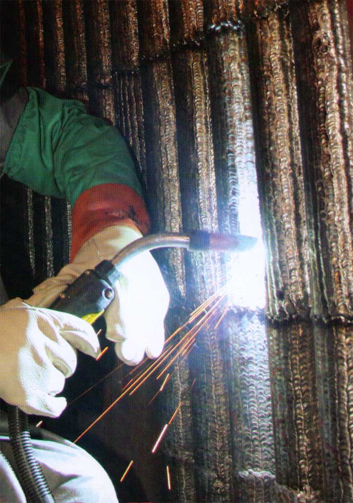
Above
Photo: This sad, manual clad weld photo was taken in 2008
and proudly displayed on the cover of a welding magazine. The clad article was
about the wonderful, new, 2008 pulsed MIG equipment available from Miller Electric
and the suitability of this equipment to this clad application. The bottom line,
for water wall boiler tubes, this is an unnecessarily expensive, poor excuse for
a weld operation and this is not the way to produce clad welds with either Inconel
or Stainless MIG weld wires.
The clad welds in the above photo reveal
poor weld settings, poor clad practices and poor weld techniques. These narrow,
clad welds will create excess weld heat for the water walls, causing excess distortion
and boiler operation efficiency issues. The unnecessary arc starts and stops and
excess weld overlap that result from narrow weld passes will create poor weld
ties, inconsistent clad weld dilution and an excessive amount of weld surface
defects. The large amount of weld passes will create excess weld heat that will
result in unacceptable and inconsistent weld dilution and affecting the clad chemistry
and longevity of the clad protection.
Ed's
MIG weld process control approach to water wall
clad welds, using 2005 pulsed
MIG equipment
MIG
CLAD APPLICATION. BOILER
WATER WALLS.
Ed's contribution to the Power and
Waste Management
Industries.
2007:
Welding Services (WSI) Atlanta: WSI is primarily involved in repairs and  refurbishment
in the power, waste energy and nuclear industries. In terms of water wall clad
welding, WSI has clad approx. 80% of the North American boilers. Each year WSI
uses approx. one million pounds of Inconel 625-622 and 300 series stainless MIG
wires for cladding boiler water wall tubes. refurbishment
in the power, waste energy and nuclear industries. In terms of water wall clad
welding, WSI has clad approx. 80% of the North American boilers. Each year WSI
uses approx. one million pounds of Inconel 625-622 and 300 series stainless MIG
wires for cladding boiler water wall tubes.
CREATED
A NEW PATENT:
While WSI has produced some of the most innovative, automatic MIG cladding equipment
available in North America, WSI did not have a resident MIG process control expert
who had the expertise necessary to make radical improvements to it's water wall
clad MIG welds. Ed was contracted for this work by the WSI engineering manager.
In less than 6 months, as the following pictures indicate, Ed dramatically improved
the water wall overlay weld quality and a new clad weld patent was developed for
this industry
WITH CLAD WELDS, LESS IS ALWAYS BETTER:
IMPROVED
BOILER LIFE AND OPERATING EFFICIENCY: As
many in the power industry are aware, with any cladding application "less
is always better". The boilers operate more efficiently when the single
pass clad weld surface is thinner and the clad weld pass thickness is uniform
and free of weld defects. When the clad filler metals cost over $22 a pound you
also don't want to waste the product. Ed's new clad patent dramatically improved
the clad weld quality and dramatically reduced the typical single pass clad weld
thickness:
DRAMATICALLY
REDUCED CONSUMABLE WELD COSTS.
With
Inconel clad wires at approx. $22 per-pound and large areas to be clad, weld consumables
are typically a large part of the cost of a boiler clad application. Ed's new
procedure reduced the amount of clad weld overlay typically
required by approx. 28%.
SINGLE
PASS CONTROLLED CLAD WELD DILUTION:
With
water wall clad applications, the minimum, "single
pass" Inconel weld clad chemistry required is 20% chrome. To attain
the minimum chrome requirements, the pulsed MIG weld procedures with
the vertical down clad welds had to attain minimum weld dilution <
8%, with consistent weld fusion on the carbon steel
boiler tubes.
ATTAIN
HIGH DEPOSITION RATES:
Of
course when cladding large areas sometimes 1000 to 10.000 sq. feet, the clad weld
process improvements must also from a weld deposition rate perspective be cost
affective. Ed's new patented clad procedure with the unique, WSI automated weld
equipment, enabled a single operator controlling two guns to deposit 26 - 28 lbs/hr.
Unless
you sell clad weld consumables,
with
clad welds on boilers, less is always better.
The
picture below was considered an optimum,
Inconel 622, Vertical Down, Pulsed
Clad MIG weld.
After
pulsed MIG weld process improvements. The final Inconel 622, single pass, clad
weld results were developed by Ed in 2006.
Ed's
MIG clad welds. Note the smooth clad surface and improved weld ties ins. This
clad application was delivered from a low cost, $6000 pulsed MIG power source
in 2006. This clad weld has a smooth finish similar to a $250.000 laser - powder
clad overlay. In contrast to the conventional water wall clad welds, Ed's process
changes required 25% less weld metal per sq/ft and for the single pass weld also
produced less weld dilution producing superior clad chemistry.
SPATTER
IS USUALLY AN INDICATION OF PROCESS CONTROL
Weld
process expertise will always ensure that any
weld process utilized runs
without weld spatter.
2006: Ed's weld on the left.
Typical clad welds on the right:
 The
vertical down 622 Inconel / stainless clad MIG welds were derived from a low cost,
six thousand dollar power source and a MIG gas mix developed
by Ed. (See gas data section). These welds also required an engineering
manager that believed that there was more to MIG welding than asking the advice
of a Lincoln / Miller sales rep or an operator throwing a switch that initiates
the arc. The
vertical down 622 Inconel / stainless clad MIG welds were derived from a low cost,
six thousand dollar power source and a MIG gas mix developed
by Ed. (See gas data section). These welds also required an engineering
manager that believed that there was more to MIG welding than asking the advice
of a Lincoln / Miller sales rep or an operator throwing a switch that initiates
the arc.
It
also helped that WSI had excellent, unique automated weld equipment that compensated
for the wire stick
out variations from the water wall curves. Ed's clad
development was complete in 2006. WSI applied for the Patent during 2006 - 2007.
Two
approaches to placing $22 a pound Inconel single pass clad welds
on a product
that costs over a hundred million dollars...
Cladding
and Hydro-Processing Vessels
2006:
Another common global clad application
overlay application influenced by Ed:
The
Electro Slag Strip Electrode Process
applying ER 347 clad welds.
The
Electro Slag Common Application.
In the refinery industry, pressure vessels used in high temperature, high pressure
"hydrogen service" such as hydrocracking
and hydrotreating are usually constructed of Chrome / Molly or Vanadium modified
Chrome / Moly steels. To overcome corrosion areas with these vessels, clad welds
of ER 347 alloy are typically applied to plate or
to wasted areas on pressure vessels.
The
most common, global cladding "process" utilized for plate cladding used
for hydrogen service, has been the Electro Slag Welding (ESW). This process uses
strip electrodes two to three inches wide. On some applications a butter layer
of ER 309 is requested followed by a surface layer of ER 347 for the clad surface.
On other applications a single layer of ER 347 is applied.
With
the ESW process, high deposition welds result from weld current > 600 amps.
The ESW process has been considered unique in that the large size of the strip
electrode results in low weld current density resulting in "low weld dilution".
The down side of this process is;
[a]
its a "single" electrode process,
[b]
It's large, cumbersome and weld position restricted,
[c] the cost of the
clad consumables and flux are high,
[d] there are few companies with expertise.
Many North American vessels are clad in Japan.
Utilizing
a unique MIG weld wire found by Ed, and cladding equipment developed by WSI, has
enabled the ability to produce "single pass",
MIG layer clad 347 welds that meet the hydrogen service 347
clad thickness, chemistry and ferrite requirements. In comparison to the
ESW and SAW process, thanks to the large differences in consumable costs and the
multi MIG gun capability, it's now possible to produce the 347 MIG clad welds,
depending on the application with a 30 to 50% cost reduction.
 In
contrast to the much more costly ESW and SAW processes, the single pass MIG clad
procedure developed by Ed and WSI enables cladding on a much wider range of applications,
and allows the flexibility to provide the vessel cladding at any site locations.
This dramatically reduces the vessel lead times or shipping costs to have this
work done. In
contrast to the much more costly ESW and SAW processes, the single pass MIG clad
procedure developed by Ed and WSI enables cladding on a much wider range of applications,
and allows the flexibility to provide the vessel cladding at any site locations.
This dramatically reduces the vessel lead times or shipping costs to have this
work done.
ED'S
MIG PROCESS EXPERTISE CHANGED
THIS TRADITIONAL GLOBAL 347 ELECTRO SLAG
AND
SAW WELD CLAD APPLICATION.
To
a clad MIG process that's faster, provides less distortion,
has less heat
effect on the steel, costs less and is more versatile.
MIG
Cladding in the 1980's.
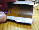
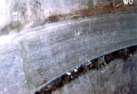
In
the 1980s, long before the development of pulsed MIG, Ed produced the Inconel
622 MIG clad weld shown in the left photo (cross section of a boiler tube). In
his clad weld there was no metallurgical evidence of a heat affected zone as evidence
in the macro. On the right photo is the MIG clad weld fusion profiles that the
power industry was accustomed to in 2008.
Ed's
Inconel clad weld on the left was made
without any cooling medium and made
with a MIG process developed in 1963.
1983 This
622 MIG clad weld made by Ed and and his good buddy Zugy, surprised the Foster
Wheeler metallurgist who examined it, as their was no evidence of the 622 weld
dilution with the carbon steel base alloy, or any evidence of a weld's heat affected
zone.
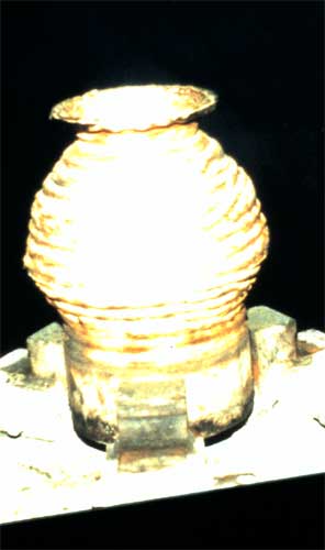
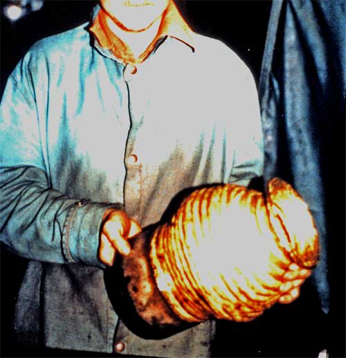
We
never had MIG equipment bells and whistles in the 1980s, yet we did have weld
process expertise and low cost MIG weld equipment developed in the 1960s. In those
days we were producing welds that are still are not produced 30 years later. In
1980 if you wanted a vessel made from aluminum bronze you ordered a solid bar
stock and spent many hours ID and OD machining, or you had it cast at a foundry
and waited 3 or 4 months. Of course you could have or called Ed and his good buddy
Zugy and they would show you how with a few pounds on alum bronze 0.045 weld wire,
in a few hours you could make the part strictly out of weld metal. If you needed
a small vessel comprised of two different alloys such as the one show above, in
which one half was Hastelloy and the other half was 316 stainless you could have
spent weeks figuring out how to make it and a small fortune in machining or you
could have called Ed and Zugy and in less than a day the product would have been
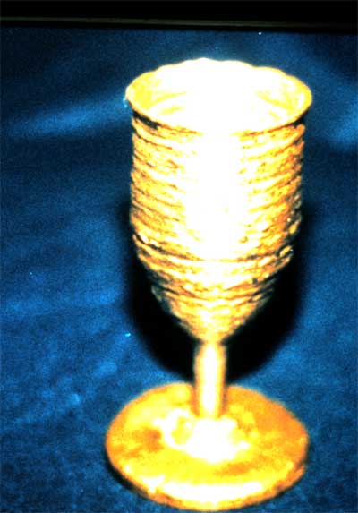
made from Hastelloy and stainless weld wire. Of course if you wanted to find the
holy grail of welding, Ed and Zugy would have taken some Titanium weld wire and
in three hours made the chalice from Titanium weld wire.
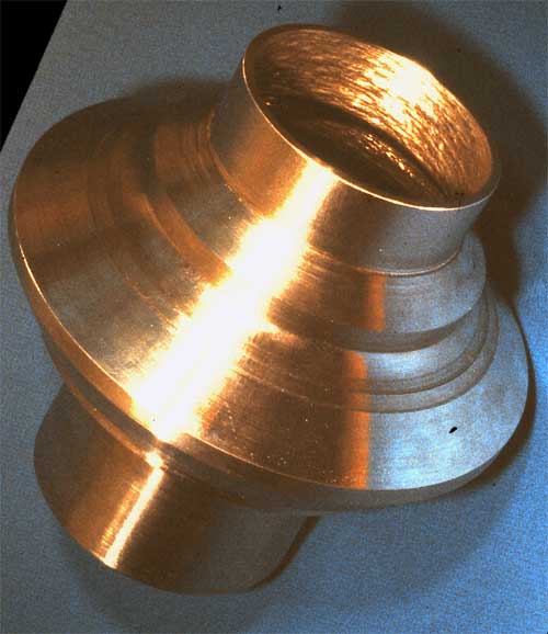
Today
we will go where no man has gone before,
however
if you have to take weld advice from salesman, or your weld
personnel "play"
with weld settings,
the consequences can be costly...
When
you have a clad welding challenges on those ID-OD power plant, refinery, and well
head equipment such as ID welds on adapter flanges,bonnets, studded tees, tree
caps, weld neck flanges, gate valves, please note, you can invest hundreds of
thousands of dollars in sophisticated overlay equipment and never quite get that
application the way it could be. You could ask a salesman for your pulsed clad
MIG advice, or you could learn how to control this important process
and produce clad welds without weld rework.
|