Written by Ed Craig:
Home page of www.weldreality.com.
PIPE
/ TUBES..ASTM - API Carbon & Low Alloy Steels.
Also a look at the effectiveness of codes and weld procesess.
PIPE Welding Steels and TIG - MIG and Flux Cored Welds.
Every pipe weld application has unique requirements guided
by different codes and specifications. The following pipe weld guide is intended
as a quick reference to assist with logical welding decisions. The information
provided, is certainly incomplete and implies no guarantees.
All
pipe and pressure vessel recommendations should be verified by the applicable
codes, especially when heat treatment, low hydrogen and low alloy electrodes are
required. No pipe weld should be carried out unless that weld is first qualified.
If the weld is required to match the properties of the pipe ensure the alloy content
of the electrode is matched and verify the preheat or post heat recommendations.
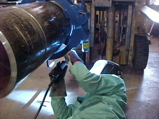
With the introduction of TIP TIG into the USA, pipe shops now have a single, easy to use process that will produce superior weld results than regular TIG, flux cored or any MIG weld trasfer mode.
.jpg) When
welding low and medium carbon steels, the 70XX stick electrodes, E70S-3-6 MIG
wires and E7XT-X flux cored electrodes can be used. When
welding low and medium carbon steels, the 70XX stick electrodes, E70S-3-6 MIG
wires and E7XT-X flux cored electrodes can be used.
When welding low alloy 1.25%
Cr - 0.5 Mo or 2.25 Cr - 1% Mo steels with up to 0.05% max
carbon, typically 8018-B2L / 9018-B3L (L = low carbon) can be used.
When
welding higher strength alloys or when tempering and quenching are required to
attain the higher strengths, the higher carbon 8018 B2 and 9018 B3 electrodes are
utilized.
- The preheat temperatures
provided are when low hydrogen electrodes are used. Consider all the TiP TiG, MIG and gas
shielded flux cored electrodes as low hydrogen consumables.
-
Preheat also applies to minimum inter-pass temperatures.
-
Post heat increases toughness and reduces residual stresses.
-
For critical pipe applications always adhere to to code and material specifications
and weld requirements. Double check the electrode recommendations.
-
1000 psi = ksi x 6.894 = MPa.
-
API 1104 is Standard for welding pipe lines.
|
For more pipe welding data follow this link
|
Steels | Yield
ksi | Tensile
ksi | Description |
| API
5A F25 | 25 | 40 | casing
drill | | API
5A H40 | 40 | 60 | |
| API
5A J55 | 55 | 75 | |
| API
5A N80 | 80 | 100 | |
| API
5A P105 | 105 | 120 | |
| API
5A P110 | 110 | 125 | |
| API
5A D | 55 | 95 | |
| API
5A E | 75 | 100 | |
COMMON PIPE ELECTRODES
E6010 Minimum Yield 50,000 psi Minimum Tensile 62,000 psi.
E6011 Minimum Yield 50,000 psi Minimum Tensile 62,000 psi.
E7010 Minimum
Yield 60,000 psi Minimum Tensile 72,000 psi.
E7018 Minimum Yield 60,000 psi
Minimum Tensile 72,000 psi.
API 5 L. Line Pipe Specification
API
5LX 5L = Line Pipe
API 5LX X = High Test Line Pipe.
|
E70S-3
and E70X6 MIG Wires.
Minimum Yield 60,000 psi, Minimum Tensile 72,000 psi
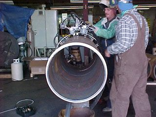
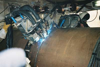
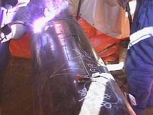
Ed
providing MIG and FCAW process control training
to Imperial oil pipe welders on 16 inch nat gas pipe
|
Steels | Yield
ksi | Tensile
ksi
MPa | PREHEAT | chemistry | weld
electrode | | API
5L X65 | >65 | | >25
mm
200F if
E60XX used | | E60XX
| API
5L A25
C1.1-C1.2 | >25 | >45
>310 | >25
mm
200F if
E60XX used | carb
0.21
Mn0.3/0.6 | |
| API
5L A | >30
206 | >48
330 | E60XX
used
>12mm 100F >25mm 200F | carb
0.21/0.22
Mn0.9 | |
| API
5L B | >35
242 | >60
413 | E60XX
used
<12mm 100F
>12mm 200F | carb
0.26/0.27
Mn1.15 | E60XX |
| API
5L X42 |
>42 | >60
413 | If
carb <0.25 with E60XX
>12mm 100F
>25mm 200F
If
carb >0.25 with E60XX PREHEAT<12 MM 100f >12mm 200F if low hyd used <12
mm 50F >12mm 150F | carb
0.29
Mn1.25 | E60XX
E70XX
E71T-1 | | API
5L X46 | >46
317 | >63
434 | E60XX
preheat
>12mm 100F
>25mm 200F
if low hyd used <12 mm 50F
>12mm 150F | carb
0.2-0.31
1.25/1.35Mn | E60XX
E70XX
E71T-1 | | API
5L X52 | >52
358 | 66
- 72
| E60XX
preheat
>12mm 100F
>25mm 200F
if low hyd used <12 mm 50F
>12mm 150F | carb
<0.31
Mn1.35 | E60XX
E70XX
E71T-1
| | API
5L X56 | >50
344 | 71-
75
517 | preheat
E60XX
carb <0.21
<12mm 100F
>12mm 150F
preheat
carb
>0.21
<12mm 100F
>12mm 200F
low hyd used carbon >0.21
<12mm 50F >12mm 150F
| carb
<0.26
Mn1.35
Cb 0.005
V0.02
Ti 0.03 | E60XX
E70XX
E71T-1 | | API
5L X60 | >60 | 75
- 78
537 | PREHEAT
SAME AS
X56 | carb
<0.26
Mn1.35
Cb 0.005
V0.02
Ti 0.03 | E60XX
E70XX
E71T-1 | | API
5L X65 | >65 | 77
- 80 | PREHEAT
SAME AS
X56 | carb
<0.26
Mn1.4
Cb 0.005
V0.02
Ti 0.03 | E60XX
E70XX
E71T-1 | | API
5L X70 | >70 | >82
567 | PREHEAT
CARB <0.2
<12mm
50F
>12mm 100F
PREHEAT CARB >0.2
<12mm
50F
>12mm 200F | carb
<0.23
Mn1.6
Cb 0.005
V0.02
Ti 0.03 | E7018
E71T-1 | | API
5L X80 | >80 | 90
- 120 | <12mm
50F
>12mm 150F | | E7018
E71T-1 |
WELD CODES, EFFECTIVENESS AND INADEQUATE INFOMATION.
 When
it comes to MIG and flux cored welding, rather than providing weld process resolutions,
most codes relevant to pipe welding will provide inadequate information or the information they provide simply adds to the global weld process myths and confusion. When
it comes to MIG and flux cored welding, rather than providing weld process resolutions,
most codes relevant to pipe welding will provide inadequate information or the information they provide simply adds to the global weld process myths and confusion.
Welding
decision makers often look codes such as AWS - API and - ASME to provide practical, pipe welding
advice and recommendations. Those individuals that that put all their faith in the codes that are governing the specific weld applications they are working on, need to be aware of a little weld reality, The weld information in these codes has too frequently been written and influenced by
code committee individuals who lacked MIG / Flux Cored weld process controls & best practices / application expertise.
50 YEARS
AFTER THE INTRODUCTION OF THE "MIG PROCESS",
AND 35 YEARS AFTER
THE INTRODUCTION OF FLUX CORED ELECTRODES, THE PRIMARY WELD CODES WHEN ADVISING ON THESE PROCESSES STILL CREATE CONFUSION AND TOO MANY QUESTIONS.
API.
5.2.3 Pulsed Gas Metal Arc Welding (GMAW-P. This code states that the pulsed process may be used for
any material thickness and whenever the welding system is changed or the settings
on existing equipment are "significantly altered" then the fabricator should
verify the weld properties. The extent of verification or testing should be as agreed
between the purchaser and fabricator.
In a world in which engineering standards should apply, what the hell does significantly altered mean. In contrast to the traditionaL, two control, MIG or flux cored weld process,
there are many weld essential variables that can be readily changed when utilizing the pulsed MIG
mode. While the API code warns against a "SIGNIFICANT CHANGE" in a pulsed
settings", the real world weld decision maker needs to be aware that an insignificant, small parameter change with the highly sensitive, manual pulsed MIG mode, can have a significant influence on the weld fusion attained.
While the code bodies in 2013 have very little negative to say about pulsed MIG process, for those of you with grey hair, you may remember that these same codes typically either did not allow regular MIG or the code weld specifications made incorrect recommendations or negative comments on the use of MIG. For example, for five decades, the MIG short circuit process has been treated like a leper, yet the weld reality was and still is in 2013, the Short Circuit mode is the best weld transfer mode for carbon steel, "rotated" pipe, open root welds.
Most of the pipe shops which were embedded with the SMAW and TIG process would typically not consider using the MIG spray transfer mode for rotated pipe welds, yet the reality has been that MIG spray transfer on the rotated pipe applications should provide superior weld fusion and less porosity than any pulsed MIG transfer.
2103: GLOBAL CODES PROVIDE NO INFORMATION ON THE POOR
PULSED MIG WELD MASS TO WELD ENERGY RATIO:
What most weld decision makers and QA personnel are not aware, is that there is on most all position, pulsed MIG pipe weld applications thicker than 6mm, a poor ratio between the moderate pulsed MIG weld energy attained, (influenced by peak to low back ground current changes) and the high weld deposition rates that typically result. The healthy pulsed MIG weld deposition rates push the high weld speeds, (faster weld speeds don't help weld fusion) along with the resulting large weld mass (larger weld mass creates a hinderance to the weld energy produced).
For those of you moving aggressively forward with the manual pulsed MIG process for your all position pipe welds, do not be surprised even when using the highest manual welder skills, when you X-Ray those sluggish stainless or nickel alloys to find lack of fusion.
YOUR LOCAL SALES REP WONT TELL YOU THIS BECAUSE THEY ARE NOT AWARE OF IT. OPTIMUM PULSED MIG WELD FUSION WITH MANUAL WELDS WILL OFTEN BE CONSIDERED MARGINAL, AND MARGINAL WELD FUSION WILL BE MADE WORSE BY THE MANY PROCESS AND HUMAN VARIABLES THAT INFLUENCE THOSE MANUAL PULSED MIG WELDS.
THE CODE RULES SHOULD CHANGE WITH AUTOMATED PULSED MIG WELDS:
I am not aware of any code that discusses the mechanized versus
manual pulsed welding differences and the weld quality consequences of those differences. When a code body puts it's stamp of approval on a weld process such as Pulsed MIG, the code is sending the message that this
is process that's acceptable for both manual and mechanized pipe welds.
With automated pulsed MIG pipe line welds in which the use of multi-MIG guns is typical, electronic MIG power source features such as volt or current energy spikes can be applied to the weld weave dwell times. These controlled, increased weld energy spikes will improve the 5G pipe side wall weld fusion. Also the controlled pulsed MIG weld speed, the controlled, mechanized weld weaves and the constant wire stick out. are the automated features that will have a lot to do with success of the mechanized pulsed
MIG process when used for pipe line welds. Take away these important controls and as it's been for three plus decades the manual pulsed MIG process has proven that the attainment of 100% X-Ray all position pipe weld quality is a challenge. By the way this is a challenge that weld shops in 2013 do not have to face when they can use the far superior TiP TiG manual or automated weld process.
API. 5.2.2 Short Circuiting
Gas Metal Arc Welding (GMAW-S). The use of GMAW-S shall be limited to the following
conditions:
[] For vertical welding, the root pass and second
pass progression for a material of any thickness may be either uphill or downhill.
Ed's response. There is no logic in using MIG short circuit, with the vertical up position on any weld application. Just as there is no logic in this cold process being used for the second pass which from a weld fusion potential is the most sensitive part of any pipe weld..
[] The fill and cap pass for butt or fillet welds may be welded with the short circuit
process, provided the thickness of any member does not exceed 3/8 in. (9.5 mm)
and vertical welding is performed with uphill progression.
Ed's response. Watch out for lack of weld fusion with the short circuit process welding vert up on any steel parts > 1/8 (> 3 mm0..
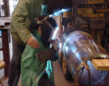
Ed testing both the short circuit and STT process
at the difficult 5 to 7 o'clock
position
MIG short
circuit welding vertical down, while fine for a rotated pipe, open root welds, this process when utilized in the fixed 5G
position can cause root problems between 5 to 7 o'clock over head positions. In this location, unmelted wire will occasionally sticks through the open root gap and root weld suck backs may occur.
In
2001, when I wrote this, the most widely used codes made no mention of the use of Spray Transfer, Globular Transfer, STT
or metal cored wires, does that mean they can or cannot be used. or does it mean that the people who write the code weld data have nothing to say on the processes that weld the pipes in the industries the codes are utilized?
 The
weld process considerations and confusion The
weld process considerations and confusion
that now surrounds pipe welding.
QUESTION.
2001: Ed when welding pipes we could use SMAW electrodes, flux cored
or metal cored electrodes. We use MIG short circuit, globular, spray, pulsed transfer. We also utilize GTAW
the Lincoln STT MIG process and sometimes SAW. As much of the welding process information
we get is sales driven and the codes are no help, can you shed some light on the subject of logical weld
process and electrode selection for code quality welds?
ANSWER.
Obviously with the many process - consumable choices. many factors have to be considered before selecting a weld process or
electrode for pipe welding. When it comes to pipe welding the first question that should be addressed is which weld process is the best process for welding pipes. I could readily write a book on this subject or I can simply say this. Visit www.tiptigusa.com and see a pipe weld quality and productivity never attained with with any of the conventional weld processes used throughout the global pipe welding industry...
SMAW GENERAL PIPE DATA CARBON STLS:
Best process for any pipe open root or fill pass is always TiP TiG.
If you have to use SMAW, the following is a little relevant root data.
Typical
Vert Down Root Electrodes, E6010 or E7010 DC+.
Consider E6010 or E7010 DC- if weld burn through or hollow bead occurs.
Typical Vert Down Filler electrode, E7010 DC+. For vert up filler passes E7018.
Use E6010 or E7010 on pipe to API 5LX65.
Over
65 yields, use low hydrogen electrodes.
Minimum preheat if pipe less than 40F use 100F to take away possible moisture.
When preheat used ensure that's also the minimum inter-pass temp.
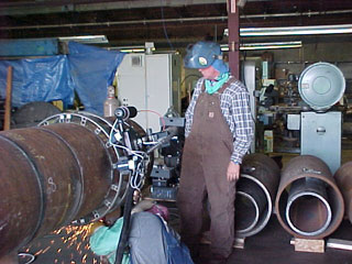
Ed testing processes - consumables on Nat Gas pipe welds.
What is
Yield strength?.
The stress that can be applied to a base metal or weld without permanent deformation
of the metal.
What is Tensile
strength?. The ulltimate tensile strength, is the maximum tensile strength
that the metal or weld can with stand before failure occurs.
What is lamellar tearing?. When welding, the weld
shrinkage stresses impose tensile strains in the steel plate or on inclusions
paralleled to the plate surface. The tensile strains can separate the inclusions
causing cracks. Excessive strains can further elongate the cracks. Carbon, manganese
and low alloy steels made at the mill with inadequate deoxidization are sensitive
to lamellar tearing. The potential for lamellar tearing increases with the amount
of inclusions in the plates being welded. Of special concern is when the inclusions
are parallel to the plate surface. More data in ASTM A770 / A770M Standard Spec
for through thickness tension testing of steel plates.
For electrode selection examine the compatibility of the
base metal's yield - tensile strengths, and the metal's primary alloy content.
The desired weld preheat will be greatly influenced in the weld procedure used
and in the amount of weld applied. Post heat and interpass temp control is typically
applied to low alloy steels when applications are subject to high and low temperatures
or high pipe pressures.
|
Mechanical
Strength of Gas Shielded Flux Cored Electrodes from the ANSI / AWS A5.29. 1198
Specifications for Low Alloy Steel Electrodes for Flux Cored Arc Welding.
| AWS Classification | Tensile
ksi | Tensile
MPa | Yield
ksi | Yield
Mpa | E6XTX-X-XM
| 60
- 80 | 410
- 550 | 50 | 340 |
E7XTX-X-XM
| 70
- 90 | 480
- 620 | 58 | 400 |
E8XTX-X-XM
| 80
- 100 | 550
- 690 | 68 | 470 |
E9XTX-X-XM
| 90
- 110 | 620
- 760 | 78 | 540 |
E10XTX-K9-K9M
| SEE
SPEC | | 88 | 610 |
M
= an argon mix with 75 to 80 argon balance CO2
| All
DCEP | E71T-1
Second number
1 = all position
| E70T-1
Second number
0 = flat and horizontal | |
What is Hardness? The
resistance of a metal or of a weld to penetration. Hardness is related to the
strength of the metal. A good way to test a weld after the weld and heat treatment
are complete. is to test the hardness of weld and the base metal HAZ surrounding the
weld.
What is Ductility? The
amount that a metal or weld will deform without breaking. Measured on welds by
the % of elongation in 2 inch 51 mm test piece. An E71T-1 flux cored electrode
should result in a minimum of 20% elongation. An E70S--6 MIG weld should produce
22%.
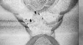 What is weld Porosity? Weld
porosity, a cavity discontinuity that forms from a weld gas reaction. The weld
porosity can be trapped inside the weld or at the weld surface. The porosity is typically
round in shape but can also be elongated or any shape. What is weld Porosity? Weld
porosity, a cavity discontinuity that forms from a weld gas reaction. The weld
porosity can be trapped inside the weld or at the weld surface. The porosity is typically
round in shape but can also be elongated or any shape.
CLUSTER WELD POROSITY. A localized
group of pores with random distribution.
Causes. Arc blow, gas flow inconsistency,
intermittent material or wire contamination, poor weld parameters or technique.
PIPING WELD POROSITY. The
pore length is longer than it's width. Often in fillet welds the pore is seen
working its way from the root towards the weld surface. Typical porosity when
using argon oxygen mixes on parts >6 mm. Increase weld energy, slow weld speed
avoid weaves.
ALIGNED
WELD POROSITY. Linear porosity, an array of round pores
in a line. Typically caused from contamination in the metal or electrode. Add
energy use arc to break up surface ahead of weld.
ELONGATED
WELD POROSITY ( wagon tracks). Typically found parallel
to weld axis. Classic porosity when moisture is evident in gas shielded flux cored
wires. Increasing the flux cored wire stick out and increasing the wire feed rate
will help. Baking flux cored wires and storing wires in a dry environment also
reduces potential. For MIG welding slow weld speeds, make welds larger, avoid
weaves, add energy to decrease weld cooling rate.
SCATTERED
WELD POROSITY. Porosity
scattered randomly throughout the weld. If the weld surface is gray and looks
oxidized it's typically insufficient gas flow. If the weld surface looks as clean
as normal the scattered porosity is usually caused by part or electrode contamination,
or weld data that causes the weld to freeze too rapidly
LARGE
PORE WELD POROSITY. If weld surface is clean and does not
look oxidized, the large pore MIG / FCAW porosity is usually a result of excessive
gas flow, gas turbulence with gas flow greater than 40 cuft/hr. If weld surface
dirty the cause is often a result of insufficient gas less than 20 cuft /hr.
PRE
HEAT ALSO MEANS MINIMUM INTER-PASS TEMPERATURE
|
Steels | Yield
ksi
MPa | Tensile
ksi
MPa | Description | PREHEAT | UNS# | weld
Chemistry
Electrode | ASTM
A53
Types E-S Grade A | | | Black
and hot dipped galvanized pipe | | Grade
A
K02504 | |
A53
Types E-S Grade B | | | | | Grade
B
K03005 | |
A53
Type E
Grade A | Grade
A-B
>30
206 | Grade
A-B
>48
331 | | Pre
heat
not Req | |
Carbon 0.25
Mn 0.95
E60XX
E70XX
E70S-6
E71T-1 |
A53
Type E
Grade B
| Grade
A-B
>30
206 | Grade
A-B
>48
331 | | preheat
>25mm
100F | | carb
0.30
Mn 1.2
E60XX
E70XX
E70S-6
E71T-1 |
A53
Type S
Grade A | >35
241 | >60
413 | | Pre
heat
not Req | | carb
0.25
Mn 0.95
E60XX
E70XX
E70S-6
E71T-1 |
A53
Type S
Grade B | >35
241 | >60
413 | | preheat
>25mm 100F | | carb
0.3
Mn 1.2
E60XX
E70XX
E70S-6
E71T-1 |
ASTM
A105 | | | | | | Weld
same as A53 | ASTM
A106-A | >30
206 | >48
330 | Seamless
Carbon High Temp Service | | KO2501 | Carb
0.25
Mn 0.93
E7018
E70S-6
E7XT-X |
| A106-B | >35
241 | >60
413 | | preheat
>25mm 100f | K03006 | Carb
0.3
Mn 1.06
Si 0.1min
E7018
E70S-6
E7XT-X |
| A106-C | >40
275 | >70
482 | | preheat
12-25mm
100F >25 mm 200F | K03501 | Carb
0.3
Mn 1.06
Si 0.1min
E7018
E70S-6
E7XT-X |
| A106 | | | | Over
0.25 Carbon
Post heat 1200F | | E7018
E70S-6
E7XT-X | ASTM
A120 | Similar
to A53 | | Steel
Black Pipe, HOT Dipped or galvanized | | | Not
specified
If galvan
use E70S-3 |
ASTM
A134 | Conforms
with A285 | | Steel
Pipe arc welded over 40 cm | | | E7018
E70S-6
E7XT-X | ASTM
A135-A | >30
206 | >48
330 | Steel
Pipe Resistance
Welded | | |
Carbon
0.25
Mn 0.95
E60XX
E7018
E70S-6
E7XT-X |
| A135-B | >35
241 | >60
413 | | | | Carbon
0.3
Mn 1.2
E60XX
E7018
E70S-6
E7XT-X |
ASTM
A139-B | >35
241 | >60
413 | Steel
Pipe
arc welded
>100mm | | KO3003 | carbon
0.3
Mn 1.0
E60XX
E7018
E70S-6
E7XT-X |
| A139-C | >42
289 | >60
413 | | | K03004 | carbon
0.3
Mn 1.2
E60XX
E7018
E70S-6
E7XT-X |
| A139-D | >46
317 | >60
413 | | preheat
>12mm 100F | K03010 | carbon
0.3
Mn 1.3
E60XX
E7018
E70S-6
E7XT-X |
| A139-E | >52
358 | >66
455 | | preheat
>12mm 100F | K03012 | carbon
0.3
Mn 1.4
E60XX
E7018
E70S-6
E7XT-X |
| A139-A | >30
206 | >48
330 | | | no
spec | E60XX
E7018
E70S-6
E7XT-X |
ASTM
A155 | | | High
temp pipe | | | E60XX
E70XX
E70S-6
E71T-1 | ASTM
A161 | >26
179 | >47
324 | Steel
Tubes
Refinery Service | | K01504 | carbon
0.1/0.2
Mn 0.3/0.8
Si 0.25max
E7018
E70S-6
E7XT-X |
| A161-T1 | >30
206 | >55
379 | | preheat
25/50mm 100F
50/100mm 200F
Post Heat required 1200F | K11522 | carbon
0.1/0.2
Mn 0.3/0.8
Si 0.1/0.5 Mo0.44/0.65
E7010-A1
E7018-A1
E8XT-X | ASTM
A178-A | NOT
SPEC | | Carbon
Steel Boiler Tubes
12 to 125mm | | K01200 | carbon
0.06/0.18
Mn 0.27/0.63
E7018
E70S-6
E7XT-X |
| A178-C | >37 | >60
413 | | | K03503 | carbon
0.35
Mn 0.8
E60XX
E70XX
E70S-6
E7XT-X |
ASTM
A179 | no
spec | | Heat
Exchanger
Condenser Tubes 3 - 75 mm OD | | K01200 | carbon
0.06/0.18
Mn 0.27/0.63
E60XX
E70XX
E70S-6
E7XT-X |
ASTM
A192 | no
spec
approx
>26 |
>47 | High
Pressure Boiler Tubes 12 - 175 mm OD | refer
to coded | K01201 | carbon
0.06/0.18
Mn 0.27/0.63
Si 0.25max
E7018
E70S-6
E7XT-X |
ASTM
A199 | | | Alloy
steel heat exchanger Tubes | <12mm
200F
>12mm 350F
Post heat req 1300F | S50200 | |
ASTM
A199
T3b | >25
172 |
>60
413
| | <12mm
200F
>12mm 350F
Post heat req 1300F | K21509 | carbon
0.15max
Mn 0.3/0.65
Si 0.5 max
Cr 1.65/2.35
Mo 0.44/0.6
E9018-B3
E9XT-1-B3 | ASTM
A199
T4 | >25 | >60 | | <12mm
200F
>12mm 350F
Post heat req 1300F | K31509 | carbon
0.15max
Mn 0.3/0.6
Si 0.5/1
Cr 2.1/2.8
Mo 0.44/0.65
E9018-B3
flux cored
E9XT-1-B3 | ASTM
A199
T5 | >25 | >60 | | <12mm
200F
>12mm 350F
Post heat req 1300F | K41545 | carbon
0.15max
Mn 0.3/0.6
Si 0.5
Cr 4/6
Mo 0.45/0.65
E9018-B3
flux cored
E9XT-1-B3 | ASTM
A199
T7 | >25 | >60 | | <12mm
200F
>12mm 350F
Post heat req 1300F | S50300 | carbon
0.15max
Mn 0.3/0.6
Si 0.5/1
Cr 6/.8
Mo 0.45/0.65
E8018-B2
flux cored
E8XT-1-B2 | ASTM
A199
T9 | >25 | >60 | | <12mm
200F
>12mm 350F
Post heat req 1300F | S50400 | carbon
0.15max
Mn 0.3/0.6
Si 0.25/1
Cr 8/10
Mo 0.9/1.1
E8018-B2
flux cored
E8XT-1-B2 | ASTM
A199
T11 | >25 | >60 | | <12mm
200F
>12mm 350F
Post heat req 1300F | K11597 | carbon
0.15max
Mn 0.3/0.6
Si 0.5/1
Cr 1/1.5
Mo 0.44/0.65
E8018-B2
flux cored
E8XT-1-B2 | ASTM
A199
T21 | >25 | >60 | | <12mm
200F
>12mm 350F
Post heat req 1300F | K31545 | carbon
0.15max
Mn 0.3/0.6
Si 0.5
Cr 2.65/3/5
Mo 0.8/1.06
E9018-B3
flux cored
E9XT-1-B3 | ASTM
A199
T22 | >25 | >60 | | <12mm
200F
>12mm 350F
Post heat req 1300F | K21590 | carbon
0.15max
Mn 0.3/0.6
Si 0.5
Cr 1.9/2.6
Mo 0.87/1.13
E9018-B3
flux cored
E9XT-1-B3 | Back
to Top
 2010: Question about Flux Cored: 2010: Question about Flux Cored:
Ed we had the following lunch room discussion. In our pipe shop we recently started to use gas shielded flux cored consumables. We used to use SMAW and we now know that the FCAW will provide superior weld fusion and deposit at least four times as much as SMAW pipe electrodes.
I found out that the flux cored wires we are using have been around for more than 25 years. Ed why did it
take many in the the pipe / pressure vessel industry so long to accept the FCAW process?
My Answer could be this simple by using one of the most popular sentances found in a pipe weld shop. "Why change the way we have always done it"
The bottom line is If a company management does not have personell with weld process expertise,
then this company does not have the resources or confidence necessary to implement
a major weld process change.
The bottom line, for decades most of the oil and pipe
companies, power companies, chemical plants and pressure vessel shops lacked qualified weld management and engineers that could lead the weld shops when process change was beneficial. So it's understandable that if you walked into a pipe shop in 1960 and then walked into a pipe shop 50 years later in 2010, that when it came to welding pipes little had changed..
 As we are all aware,
many SMAW and GTAW pipe welders are often die-hard traditionalists who are proud
of their manual skills and often less than enthusiastic to make a change to a process
which requires process expertise and different best weld practices. As we are all aware,
many SMAW and GTAW pipe welders are often die-hard traditionalists who are proud
of their manual skills and often less than enthusiastic to make a change to a process
which requires process expertise and different best weld practices.
For example, the SMAW welders would try the flux cored wires,
and not undersatnding the process requirements they would then play around with the data and MIG equipment controls. Without
optimum settings the flux cored consumables would not perform the way they were
designed to perform. The stick welders would be disgruntled with the FCAW process and resist the apathetic
attempts by the inexperienced weld management to make the cost affective weld process changes.
|
Steels | Yield
ksi | Tensile
ksi | Description | PREHEAT | UNS# | weld
Electrode | ASTM
A200
| >25
172 | >60
413 | Alloy
steel Tubes Refinery | Heat
treat and weld similar to A199 | S50200 | Weld
similar
to A199 ensure chrome Mo levels compatible |
ASTM
A200 T3b
| >25 | >60 | | | K21509 | carbon
0.15
Mn 0.3/0.65
Si 0.5
Cr 1.65/2.35
Mo 0.44/0.65 |
ASTM
A200 T4
| >25 | >60 | | | K31509 | carbon
0.15
Mn 0.3/0.6
Si 0.5/1.0
Cr 2.15/2.8
Mo0.44/0.65 |
ASTM
A200 T5
| >25 | >60 | | | K41545 | carbon
0.15
Mn 0.3/0.6
Si 0.5
Cr 4/6
Mo0.45/0.65 |
ASTM
A200 T7
| >25 | >60 | | | S50300 | carbon
0.15
Mn 0.3/0.6
Si 0.5/1
Cr 6/8
Mo0.45/0.65 |
ASTM
A200 T9
| >25 | >60 | | | S50400 | carbon
0.15
Mn 0.3/0.6
Si 0.25/1
Cr 8/10
Mo0.9/1.1 |
ASTM
A200 T11
| >25 | >60 | | | K11597 | carbon
0.15
Mn 0.3/0.6
Si 0.5/1
Cr1/1.5
Mo0.44/0.65
E8018-B2 | ASTM
A200 T21
| >25 | >60 | | | K31545 | carbon
0.15
Mn 0.3/0.6
Si 0.5
Cr2.65/3.35
Mo 0.8/1 |
ASTM
A200 T22
| >25 | >60 | | | K21590 | carbon
0.15
Mn 0.3/0.6
Si 0.5
Cr1.9/2.6
Mo 0.87/1.13 |
Back
to Top
STRESS
RELIEVING (SR). BASIC GUIDELINES:
STRESS
RELIEF - CONTROLLED HEATING & COOLING TO REDUCE STRESS.
STRESS
RELIEF MACHINED PARTS FOR DIMENSIONAL STABILITY.
STRESS
RELIEF SLOW HEATING AND COOLING REQUIRED
CONFIRM
WITH CODE SPECIFICAIONS FOR STRESS RELIEF REQUIREMENTS.
TYPICAL
STRESS RELIEF SOAK TIME
ONE HOUR PER INCH OF THICKNESS
| SR
HEAT & COOL RATE PER HOUR 400oF 204oC DIVIDE THICKER PART
|
PARTS
OF DIFFERENT THICKNESSES
SR MAX TEMP DIFFERENCE 75oF 24oC
| STRESS
RELIEF CARBON STEELS 1100oF 593oC
TO 1250oF 677oC
|
STRESS
RELIEF CARBON 0.5% Mo
1100oF 593oC TO 1250oF 677oC
| SR
1% CHROME 0.5% Mo
1150oF 621oC TO 1325oF 718oC
|
SR
1.25 % CHROME 0.5% Mo
1150oF 621oC TO 1325oF 718oC
| SR
2% CHROME 0.5% Mo
1150oF 621oC TO 1325oF 718oC
|
SR
2.25 % CHROME 1% Mo
1200oF 649oC TO 1375oF 746oC
| SR
5% CHROME 0.5% Mo
1200oF 649oC TO 1375oF 746oC
|
SR
7% CHROME 0.5% Mo
1300oF 704oC TO 1400oF 760oC
| SR
9% CHROME 1% Mo
1300oF 704oC TO 1400oF 760oC
|
SR
12% CHROME 410 STEEL
1550oF 843oC TO 1600oF 871oC
| SR
16% CHROME 430 STEEL
1400oF 760oC TO 1500oF 815oC
|
SR
9% NICKEL
1025oF 552oC TO 1085oF 585oC
| FOR
300 SERIES STAINLESS SR WILL
RESULT IN CARBIDE PRECIPITATION
|
WITH
LOW CARBON 300 SERIES
MAX SR 1050oF 566oC
| SR
400 SERIES CLAD STAINLESS
1100oF 593oC TO 1350oF 732oC
|
SR
CLAD MONEL INCONEL Cu NICKEL
1150oF 621oC TO 1200oF 649oC
| STRESS
RELIEF MAGNESIUM AZ31B 0
500oF 260oC 15 MIN
|
STRESS
RELIEF MAGNESIUM AZ31B
H24 300oF 149oC 60 MIN
|
HK31A H24
550oF 288oC 30 MIN
HM21A T8-T81 700oF 371oC 30 MIN
|
MAGNESIUM
WITH MORE THAN 1.5%
ALUMINUM STRESS RELIEF
| MAGNESIUM
CAST ALLOYS AM100A
500oF 260oC 60 MIN
|
AZ-63A
81A 91C & 92A
500oF 260oC 60 MIN
| |
Should a weld professional in a a pipe / pressure vessel shop be able to tell you;
[a] the 0.045 (1.2mm) and 0.035 (1 mm) MIG wire feed position and weld voltage which is the
starting point for spray transfer? These are good settings for rotated pipe fill passes.
[b] the 0.045 gas shielded E71T-1
optimum single wire feed setting and voltage for producing a 6 mm, vert up fillet weld on a plate. This is the same setting for welding anny steel pipe vertical up.
If an industry, in which many of it's educators, engineers and managers places little importance
in weld process control training, why
should we expect welders to focus on the weld process control or best practices details.
|
Steels | Yield
ksi
MPa | Tensile
ksi
MPa | Description | PREHEAT | UNS# | weld
Electrode
chemistry | ASTM
A209 | | | Carb
Moly Boiler Super
Heater Tubes | Post
Heat req 1150 to 1350F | |
| ASTM
A209 T1 | >30
206 | >55
379 | | preheat
>25mm
150F | K11522 | carb
0.1/0.2
Mn 0.3/0.8
Si 0.1/0.5
Mo0.44/0.65
E7018-A1
E8XT-1-A1
E80S-6 |
ASTM
A209 T1a | >32
220 | >60
413 | | preheat
12-25mm
150F
>25mm
250F | K12023 | carb
0.15/0.25
Mn 0.3/0.8
Si 0.1/0.5
Mo0.44/0.65
E7018-A1
E8XT-1-A1
E80S-6 | ASTM
A209 T1b | >28
193 | >53
365 | | preheat
>25mm
150F | K11422 | carb
0.14max
Mn 0.3/0.8
Si 0.1/0.5
Mo0.44/0.65
E7018-A1
E8XT-1-A1
E80S-6 |
Why in the welding industry is it difficult to find anyone in management who
knows
the real cost of a MIG or flux cored weld?
The weld industry management weld cost focus is too often on something easy to understand like the cost of the weld wire or gas mix, rather than on the MIG or flux cored, semi-automatic weld deposition rates attained. When I first bought TiP TiG to North America and discussed with weld shop owners the weld deposition rate differences between TiP TiG and GTAW - FCAW and pulsed MIG, I would too often see the glaze look in the manager's or engineer's eyes. Thats the same look I see in my wifes eyes when i chat to her about welding
When an industry
ignores or is not aware of the weld process / application weld deposition rate potential, it's understandable when the real cost of a weld is rarely understood.
|
Steels | Yield
ksi
MPa | Tensile
ksi
MPa | Description | Preheat | UNS# | Weld
Electrode
Chemistry | ASTM
A210 | | | Medium
Carbon Stl Boiler Super Heater
Tubes 12mm 125mm OD | | | |
ASTM
A210 A-1 | >37
255 | >60
413 | | Check
ASME
Code | K02707 | carb
0.27max
Mn 0.93
Si 0.1
Mo0.44/0.65
E70XX
E70S-6
E71T-1 | ASTM
A210 C | >40
275 | >70
482 | | | K03501 | carb
0.35max
Mn 0.29
Si 0.1
Mo0.44/0.65
E70XX
E70S-6
E71T-1 | ASTM
A211 | | | Mild
steel pipe | | | E60XX
E70XX
E70S-6
E71T-1 |
 What
shortage of skilled welders. What
shortage of skilled welders.
The manager
states, "how will we ever replace this aging, highly skilled weld workforce"?
TIG - MIG and FCAW Weld Reality:
With all the issues that
occur with welding, managers often perceive that the weld
processes used in the weld shop must be complex, after all, these processes have been around for decades, yet the weld personel seem to have to play around with the weld controls whenever a new application comes into the weld shop.
THE PIPE SKILLED SHORTAGE WELD REALITY:
It's important to note that for code quality pipe welds, that the TIP TIG process eliminates at least 50% of the GTAW skills required for pipe welds. The majority of weld issues
that occur daily in pipe weld shops are a result of an industry
and educational system that for decades has placed minimal focus or importance on weld
process controls and best weld practice expertise.
WHY THERE SHOULD BE LITTLE CONCERN FOR SKILLED PIPE WELDER SHORTAGES:
While community colleges take many months and sometimes years to train personnel to weld pipe, the following is the weld reality. When training a suitable individual who has never welded, it would take me no more than 5 days to train a TIP TIG welder to weld all position (5G) pipes, and the same 5 days to train that person to weld the pipes with either the MIG / flux cored
process. Those trainess would then have the ability to pass any weld qualification test and meet any code requirements.
WELD PERSONNEL WHO ARE PROUD OF THEIR SKILLS SHOULD ALSO TAKE PRIDE
IN THEIR WELD PROCESS KNOWLEDGE AND IN THEIR ABILITY TO CNROLL THE WELD PROCESSES
AND CONSUMABLES THEY OPERATE.
Consider my CD process
control training resources, they are a great training aid for guys who dont want to "play around" with their weld controls..
|
Steels | Yield
ksi
MPa | Tensile
ksi
MPa | Description | PREHEAT | UNS# | Weld
Electrode
Chemistry | ASTM
A213 T2 | >30 | >60 | Ferritic
Austenitic Super heater Tubes | Preheat
300F
Post Heat 1200F | K11547 | carbon
0.2
Mn 0.61
Si 0.3
Cr 0.81
Mo 0.65
E8018-B2
E8XT1-B2 | ASTM
A213 T3-b | >30 | >60 | | Preheat
<25mm 200F >25mm 250F | K21509 | carbon
0.15max
Mn 0.65
Si 0.5
Cr2.35
Mo 0.65
E9018-B3
E9XT-B3 | ASTM
A213 T5 | >25 | >60 | | Preheat
<12mm 100F >12mm 600F
Post heat 1400F | K41545 | carbon
0.15max
Mn 0.6
Si 0.5
Cr4/6
Mo 0.65
E502T-1 | ASTM
A213 T5-b | >30 | >60 | | Preheat
<12mm 100F >12mm 600F
Post heat 1400F | K51545 | carbon
0.15max
Mn 0.6
Si 1/2
Cr4/6
Mo 0.65
E502T-1 | ASTM
A213 T5c | >30 | >60 | | Preheat
<12mm 100F >12mm 600F
Post heat 1400F | K41245 | carbon
0.12max
Mn 0.6
Si 0.5
Cr4/6
Mo 0.56
E502T-1 | ASTM
A213 T7 | >30 | >60 | | Preheat
<12mm 100F >12mm 600F
Post heat 1400F | K50300 | carbon
0.12max
Mn 0.6
Si 0.5/1
Cr6/8
Mo 0.56 |
ASTM
A213 T9 | >30 | >60 | | Preheat
<12mm 100F >12mm 600F
Post heat 1400F | k50400 | carbon
0.15max
Mn 0.6
Si 1.0
Cr 8/10
Mo 1.1
E502T-1 | ASTM
A213 T11 | >30 | >60 | | Preheat
<12mm 100F >12mm 250F
Post heat 1200F | k11597 | carbon
0.15max
Mn 0.6
Si 1.0
Cr1/1.5
Mo 0.65
E8018-B2
E8XT1-B2 | ASTM
A213 T12 | >30 | >60 | | Preheat
<12mm 100F >12mm 250F
Post heat 1200F | K11562 | carbon
0.15max
Mn 0.61
Si 0.5
Cr0.8/1.25
Mo 0.65
E8018-B2
E8XT1-B2 | ASTM
A213 T17 | >30 | >60 | | Preheat
350F >
Post heat 1100F | K12047 | carbon
0.25max
Mn 0.61
Si 0.35
Cr0.8/1.25
V 0.15
E8018-B2
E8XT1-B2 | ASTM
A213 T21 | >30 | >60 | | Preheat
400F >
Post heat 1300F | K31545 | carbon
0.15max
Mn 0.6
Si 0.5
Cr2.65/3.5
Mo 1.06
E9018-B3
E9XT-B3 | ASTM
A213 T22 | >30 | >60 | | Preheat
<12mm 150F >12mm 250F
Post heat 1300F | K21590 | carbon
0.15max
Mn 0.6
Si 0.5
Cr1.9/2.6
Mo 1.13
E9018-B3
E9XT-B3 |
| Steels | Yield
ksi
MPa | Tensile
ksi
MPa | Description | PREHEAT | UNS# | weld
Electrode
chemistry | ASTM
A214 | Not
Specified | | Carbon
Steel Heat Exchanger Condenser Tubes | | K01807 | carbon
0.18max
Mn 0.27/0.63
E60XX
E7018
E70S-6
E7XT-1 | ASTM
A226 | >26
179 | >47
324 | Carbon
steel boiler Super heater tubes 12 to 25 mm OD | | K01201 | carbon
0.16/0.18
Mn 0.27/0.63
Si 0.25max
E60XX
E70XX
E70S-3
E7XT-1 |
ASTM
A249 | | | Stainless
tubes | | | |
ASTM
A250 | | | Carbon
Moly Boiler Super heater tubes | | |
| ASTM
A250 T1 | >30
206 | >55
379 | | preheat
>25mm 100F >50mm 200F Post Heat 1200F | K11522 | carbon
0.1/0.2
Mn 0.3/0.8
Si 0.1/0.5
Mo 0.44/0.6
E7018-A1
E70T5-A1
E8XT1-A1 | ASTM
A250 T1a | >32
220 | >60
413 | | preheat
>12mm 100F >25mm 275F Post Heat 1200F | | carbon
0.15/0.25
Mn 0.3/0.8
Si 0.1/0.5
Mo 0.44/0.6
E7018-A1
E70T5-A1
E8XT1-A1 |
ASTM
A250 T1b | >28
193 | >53
365 | | preheat
>25mm 100F >50mm 200F Post Heat 1200F | K11422 | carbon
0.14max
Mn 0.3/0.8
Si 0.1/0.5
Mo 0.44/0.6
E7018-A1
E70T5-A1
E8XT1-A1 | ASTM
A252 | | | Mild
steel pipe
weld same as A53 | | | |
ASTM
A268 | | | Ferritic
stainless tube general service | | | |
ASTM
A268
Tp 405 | >30
206 | >60
413 | | | S405000 | carbon
0.08max
Mn 1.0
Ni 0.5
Cr
11.5/13.5
Al 0.1/0.3
E410 |
ASTM
A268
Tp 410 | >30
206 | >60
413 | | Pre
heat
600F
Post heat
1400, post not req if low hyd used | S41000 | carbon
0.15max
Mn 1.0
Ni 0.5
Cr11.5/13.5
E410
E310 | ASTM
A268
Tp 409 | | | | | S40900 | carbon
0.15max
Mn 1.0
Ni 0.5
E410 | ASTM
A268
Tp 329 | | | | | S32900 | E312
E309 | ASTM
A268
Tp 430 | | | | | | E430 |
ASTM
A269 | | | stainless
tubes | | | |
What is Toughness? The
ability of the metal or weld sample at a predetermined temperature to withstand
a shock. The test for toughness measures the impact of a pendulum on a
notched specimen. You may see that the required impact properties for the metal
or weld are 20ft-lbf @ -20 F (27 j @ -29C). Some things that can influence toughness
in a weld;
[]
lack of fusion.
[]
excess weld heat.
[]
porosity in welds and laminations in the steels.
[]
weld undercut.
[]
incorrect weld profiles
[] incorrect weld consumables.
| Steels | Yield
ksi
MPa | Tensile
ksi
MPa | Description | PREHEAT | UNS# | weld
Electrode
chemistry | ASTM
A333 | | | Steel
pipe
for low temp Service | | | |
ASTM
A333-1 | >30
227 | >55
379 | | Pre
heat >carb >0.26 >25mm 100F | K03008 | carbon
0.3max
Mn0.4/0.6
E7018
E70S-6
E7IT-1
E8018-C3 | ASTM
A333-3 |
>35
| >65 | | Pre
heat
150F
Post heat
1200F | | carbon
0.19max
Mn0.31max
Si 0.18/0.37
Ni3.16/3.82
E8018-C1
E91T1-Ni2 | ASTM
A333-4 |
>35
241
| >60
413 | | Pre
heat <25 mm 150F
>25 mm 300F. Post heat 1200F | KO3006 | carbon
0.12max
Mn0.5/1.05
Si 0.08/0.37
Ni0.47/0.98
Cr 1.01
Cu0.4/0.75
AL0.04/0.30
E8018-W
E80T1-Ni2 |
ASTM
A333-6 |
>35
241
| >60
413 | | Pre
heat >carb >0.26 >25mm 100F | | carbon
0.3max
Mn0.29/1.06
E8018-W
E7018
E70S-6
E7IT-1 E8018-C3
| ASTM
A333-7 |
>35
241
| >65
| | Pre
heat
150F
Post heat
1200F | K21903 | carbon
0.19max
Mn0.9max
Ni 2.03/2.57
E8018-C1
E80T5-Ni2 |
ASTM
A333-8 | >75 | >100 | | Pre
heat 200F Max inter-pass 400F | | carbon
0.13max
Mn0.9max
Si 0.32max
Ni 8.4/9.6
Mn
0.9
Ni 8.4/9.6 | ASTM
A333-9 | >46
317 | >63
434 | | Pre
heat
150F
Post heat
1200F | K22035 | carbon
0.2max
Mn 0.4/ 1.06
Ni 1.6/2.24
Cu0.75/1.25
E8018-C1
E80T5-Ni2 |
What is Fatigue?
The
ability of a metal or weld to withstand repeated loads. Fatigue failures occur
at stress levels less than the metal or weld yield strength. Some
things that can influence fatigue failure:
- Excess weld profiles.
- Welds
which cause undercut.
- FCAW
or SMAW slag inclusions.
- Lack
of weld penetration.
-
Excess weld heat, typically from multi-pass welds without inter-pass temp controls.
-
Items to a part that adds restraint while welding.
- Items
added to a part that can concentrate stresses in a specific location.
- Incorrect
selection of filler metal, weld too weak or weld too strong.
|
Steels | Yield
ksi | Tensile
ksi | Description | PREHEAT | UNS# | weld
Electrode | ASTM
A334 | | | Carbon
low alloy tubes for low tem service | | | |
ASTM
A334-1 | >30
206 | >55
379 | | Preheat
Carb >0.25
or steel >25mm 100F | K03008 | carbon
0.3max
Mn 0.4/ 1.06
E7018
E70S-6
E71T-1
E8018-C3 | ASTM
A334-3 | >35
241 | >65
448 | | Preheat
150F
>25mm 250F
post 1200F | K31918 | carbon
0.19max
Mn0.31/0.64
Si0.18/0.37
Ni 3.18/3.82
E8018-C1
E81T-1-Ni2 |
ASTM
A334-6 | >35 | >60 | | Preheat
Carb >0.25
or steel >25mm 100F | K03006 | carbon
0.03max
Mn0.29/1.06
Si0.1min
E7018
E70S-6
E71T-1 | ASTM
A334-7 | >35 | >65 | | Preheat
150F
>25mm 250F
post 1200F | K21903 | carbon
0.19max
Mn0.9max
Si 0.13/0.3
Ni 2.2 2.57
E8018-C1
E81T-1-Ni2 |
ASTM
A334-8 | >75
517 | >100
689 | | | K81340 | carbon
0.13max
Mn0.9max
Si 0.13/0.32
Ni 8.4/ 9.6
|
ASTM
A334-9 | >46 | >63 | | Preheat
150F
>25mm 250F
post 1200F | K22035 | carbon
0.2max
Mn0.4/1.06
Ni 1.6/2.24
Cu 0.75/1.25
E8018-W
E80T1-W |
What is Brittleness?
The ease at which the weld or metal will break or crack without appreciable deformation.
When a metal gets harder it becomes more brittle. Preheat, inter-pass temp controls
and post heat all are designed to reduce the potential for brittleness.
|
Steels | Yield
ksi
MPa | Tensile
ksi
MPa | Description | PREHEAT | UNS# | weld
Electrode
chemistry | ASTM
A335 | | | Ferritic
Alloy Steel pipe for high temp service | | S50200 | |
ASTM
A335-P1 | >30
206 | >55
379 | | preheat
>25mm 100F >50mm 200F | K11522 | carbon
0.2max
Mn0.3/0.86
Si 0.1/0.5
E70XX-A1
E70S-6
E71T-1 | | A335-P2 | >30
206 | >55
379 | | preheat
carb <0.15 <25mm 150F >25mm or carb >0.15 300F. Post heat >25mm
1200F | K11547 | carbon
0.2max
Mn0.3/0.61
Si 0.1/0.5
Mo0.44/0.65
E8018-B2
E80T5-B2 | | A335-P5 | >30 | >60 | | preheat
>12mm 400F post heat 1375F | K41545 | carbon
0.15max
Mn0.3/0.6
Si 0.5
Cr4/6
Mo0.45/0.65
E502T-1 |
| A335-P5b | >30 | >60 | | preheat
>12mm 600F post heat 1375F | k51545 | carbon
0.15max
Mn 0.6
Si 1/2
Cr4/6
Mo0.45/0.65
Cr4/6
Mo0.45/0.65
Si 1/2
E502T-1 | | A335-P5c | >30 | >60 | Ferritic
Alloy Steel pipe for high temp service | preheat
>12mm 600F post heat 1375F | K41245 | carbon
0.12max
Mn0.3/0.6
Si 0.5
Cr4/6
Mo0.45/0.65
Cr4/6
Mo0.45/0.65
Ti/Cu
E502T-1 |
| A335-P7 | >30 | >60 | | preheat
>12mm 600F post heat 1375F | S50300 | carbon
0.15max
Mn0.3/0.6
Si 0.5/1
Cr6/8
Mo0.45/0.65
Cr6/8
Mo0.44/0.65
| | A335-P9 | >30 | >60 | | preheat
>12mm 600F post heat 1375F | S50400 | carbon
0.15max
Mn0.3/0.6
Si 0.25/1
Cr8/10
Mo0.9/1.1
E502T-1 |
| A335-P11 | >30 | >60 | | preheat
<25 mm 150F >25mm 300F post heat 1200F | K11597 | carbon
0.15max
Mn0.3/0.6
Si 0.5/1
Cr1/1.5
Mo0.44/0.65
E8018-B2
E80T5-B2 | | A335-P12 | >30 | >60 | | preheat
<25 mm 150F >25mm 300F post heat 1200F | K11562 | carbon
0.15max
Mn0.3/0.61
Si 0.5
Cr0.8/1.25
E8018-B2
E80T5-B2 | | A335-P15 | >30 | >60 | Ferritic
Alloy Steel pipe for high temp service | preheat
>12 mm 100F >25mm 200F | K11578 | carbon
0.15max
Mn0.3/0.61
Si 1.15/1.65
Mo0.44/0.65
E7018-A1
E70S-6
E71T-1 | | A335-P21 | >30 | >60 | | preheat
400F > post heat 1350F | K31545 | carbon
0.15max
Mn0.3/0.61
Si 0.5
Cr2.65/3.35
Mo0.8/1.06
E9018-B3
E9T5-B3 | | A335-P22 | >30 | >60 | Ferritic
Alloy Steel pipe for high temp service | preheat
<25 mm 150F >25mm 300F post heat 1300F | K21590 | carbon
0.15max
Mn0.3/0.6
Si 0.5
Cr1.9/2.6
Mo0.87/1.13
E9018-B3
E9T5-B3 |
|
Steels | Yield
ksi
MPa | Tensile
ksi
MPa | Description | PREHEAT | UNS# | Weld
Electrode
Chemistry | ASTM
A369
FP1-FP2
FP3b-FP5
FP7-FP9
FP11-FP12
FP21-FP22
FPA-FPB | | | Carbon
and ferritic alloy forged bored pipe
high temp service | | | |
A369
FP1 | >30
206 | >60
413 | | preheat
>25mm 150F Post heat req 1200F | K11522 | carbon
0.2
Mn0.3/0.8
Si0.1/0.5
Mo0.44/0.65
E7018-A1
E70T5-A1 |
A369
FP2 | >30
206 | >55
| | preheat
<13mm 100F
<25mm
250F
>25mm 400F Post heat req >25mm
1200F | K11547 | carbon
0.1/0.2
Mn0.3/0.61
Si0.3
Cr0.5/0.81
Mo0.44/0.65
E8018-B2
E80T1-B2 | A369
FP3b | >30
206 | >60
413 | | preheat
>13mm 150F
<50mm 250F Post heat req 1200F | K21509 | carbon
0.15
Mn0.3/0.6
Si 0.5
Cr1.65/2.35
Mo0.44/0.65
E9018-B3
E90T5-B3 | A369
FP5 | >30
206 | >60
413 | | preheat
>12mm 600F
Post heat req 1375F | K41545 | carbon
0.15
Mn0.3/0.6
Si 0.5
Cr 4/6
Mo0.44/0.65
E502T-1 |
A369
FP7 | >30
206 | >60
413 | | preheat
>12mm 600F
Post heat req 1375F | S50300 | carbon
0.15
Mn0.3/0.6
Si 0.5/1
Cr 6/8
Mo0.44/0.65 |
A369
FP9 | >30
206 | >60
413 | | preheat
>12mm 600F
Post heat req 1375F | K90941 | carbon
0.15
Mn0.3/0.6
Si 0.5/1
Cr 8/10
Mo0.9/1.1 |
A369
FP11 | >30
206 | >60
413 | | preheat
<25mm 150F
>25mm
300F
Post heat req 1200F | K11597 | carbon
0.15
Mn0.3/0.6
Si 0.5/1
Cr 1/1.5
Mo0.44/0.65
E8018-B2
E80T1-B2 | A369
FP12 | >30
206 | >60
413 | | preheat
<25mm 150F
>25mm
300F
Post heat req 1200F | K11562 | carbon
0.15
Mn0.3/0.61
Si 0.5
Cr 0.8/1.25
Mo0.44/0.65
E8018-B2
E80T1-B2 | A369
FP21 | >30
206 | >60
413 | | preheat
500F
Post heat req 1350F | K31545 | carbon
0.15
Mn0.3/0.6
Si 0.5
Cr 2.65/3.35
Mo0.8/1.06
E9018-B3
E90T5-B3 | A369
FP22 | >30
206 | >60
413 | | preheat
<25mm 175F
>25mm
275F
Post heat req 1300F | K21590 | carbon
0.15
Mn0.3/0.6
Si 0.5
Cr 1.9/2.6
Mo0.87/1.13
E9018-B3
E90T5-B3 | A369
FPA | | | | | K02501 | E7018
E71T-1 | A369
FPB | | | | | K03006 | E7018
E71T-1 | ASTM
A381
Y35-Y42
Y46-Y48
Y50-Y52
Y56
Y60 -Y65 | 35-65 | 60-80 | High
pressure pipe | preheat
carbon <0.2 >25mm 50F >25mm 100F preheat
carbon >0.2 >25mm 150F >25mm 250F | K03013 | Carbon
0.26
Mn1.40max
Y35 To
Y56
E70XX
E71T-1
Y60
To Y65
E9018-M
|
ASTM
A405 | | | Ferritic
alloy steel pipe high temp service | | | |
A405
P24 | 30-50 | 60-80
413-551 | | preheat
<25mm 175F >25mm 300F post heat req 1200F | K11591 | carbon
0.15
Mn 0.6Ce 0.8/1.25
Mo 0.87/1.13
v 0.25
E8018-B2
E9018-B3
E80T5-B2 | ASTM
A423
1-2 | | | Low
alloy tube | | | |
ASTM
A423-1 | >37
255 | >60
413 | | | K11535 | Carbon
0.15
Mn 0.55
Si 0.1
Ni 0.2/0.7
Cr 0.24/1.31
E8018-B2 | ASTM
A423-2 | >37
255 | >60
413 | | preheat
refer to ASME | K11540 | Carbon
0.15
Mn 0.5/1
Si 0.1
Ni 0.4/1.1
Mo 0.1
Cu 0.3/1
E88018-C3 | ASTM
A426 | | | Cast
ferritic alloy pipe high temp service | | | |
What is Malleability?
The ability of a metal or weld to be permanently deformed by compression such
as in a rolling or forming operation. Ductile metals are malleable.
|
Steels | Yield
ksi
MPa | Tensile
ksi
MPa | Description | PREHEAT | UNS# | weld
Electrode
chemistry | ASTM
A426 | | | Cast
ferritic alloy pipe high temp service | | | |
A426
CP1 | >35
| >65
| | preheat
12-25mm
100F>25mm 200F post heat req 1200f | J12521 | carbon
0.25
Mn0.8
Si 0.5
Mo 0.65
E7018-A1
E70T5-A1 |
A426
CP2 | >30
206 | >60
413 | | preheat
<12mm
150F<25mm 250F >25 mm 400F post heat req 1200f | J11547 | carbon
0.2
Mn0.61
Mo 0.65
Cr 0.8 | A426
CP5 | >60 | >90 | | preheat
>12mm
600Fpost heat req 1375F | J42045 | carbon
0.2
Mn0.7
Mo 0.65
Cr 6.5
E502T-1 |
A426
CP5b | >30
206 | >60
413 | | preheat
>12mm
600Fpost heat req 1375F | J51545 | carbon
0.15
Mn0.6
Si 2
Mo 0.6
Cr 6
E502T-1 |
A426
CP7 | >30 | >65 | | preheat
>12mm
600Fpost heat req 1375F | J61594 | carbon
0.15
Mn0.6
Si 1
Mo 0.65
Cr 8 |
A426
CP9 | | | | preheat
>12mm
600Fpost heat req 1375F | J82090 | carbon
0.2
Mn0.65
Si 1
Mo 1.2
Cr 10
E505T-1 |
A426
CP11 | >40 | >70 | | preheat
<12mm
150F <25mm 250F >25mm 350F post heat req 1200F | J12072 | carbon
0.2
Mn0.65
Mo 0.65
Cr 1.5
E8018-B2
E80T-B2 |
A426
CP12 | >30
206 | >60
413 | | preheat
<12mm
100F >12mm 250F >25mm 350F post heat req 1200F | J11562 | E8018-B2
E80T-B2 | A426
CP15 | | | | preheat
>12mm
100F >25mm 200F post heat opt | J11522 | E7018-A1
E70T5-A1 | A426
CP21 | | | | preheat
<100mm
500F post heat req 1350F | J31545 | carbon
0.15
Mn0.6
Mo 1.06
Cr 3.35
E9018-B3
E90T1-B3 |
A426
CP22 | >40 | >70 | | preheat
<25mm
200F >25mm 400F post heat req 1300F | J21890 | carbon
0.18
Mn0.7
Mo 1.2
Cr 2.75
E9018-B3
E90T1-B3 |
A426
CPCA15 | | | | | J91150 | carbon
0.15
Mn 1
Mo 05
Cr 14
E410 | ASTM
498 | | | condenser
tubes
conforms to A199/A179
A213/A249/A334 | | | |
What is grain size?
A good way to demonstrate the effect of the grain size on a metal or weld. Take
a full length wooden pencil, then break it in half, now break the two halves in
two, try it again. You will note how difficult it is to break the smaller pieces.
When we weld, the heat from the weld can make the grains in the base metal elongate,
as the weld cools down the grains will get smaller. If we are doing multi-pass
welds such as welding in the vee-prep of a pipe, and we don't have inter-pass,
or post heat controls the welds may look good, however the high energy from the
mult-pass welds may result in grain size greater than that approved by the pipe
/ steel manufactures. In fatigue situations, elongated grains can influence failure.
|
Steels | Yield
ksi
MPa | Tensile
ksi
MPa | Description | PREHEAT | UNS# | Weld
Electrode
Chemistry | ASTM
A500 | | | Structural
steel cold formed tube | | | |
| A500-A |
33-39
| >45
| | | K03000 | carb
0.26
Mn 1.1
Cu 0.2min
E7018 if Cu specified
E8018W
E80T1-W |
| A500-B | 42-46 | >58 | | | K03000 | carb
0.26
Mn 1.1
Cu 0.2min
E7018 if Cu specified
E8018W
E80T1-W |
| A500-C | >46
317 | >62
427 | | | K02705 | carb
0.23
Mn 1.35
Cu 0.2min
E7018 if Cu specified
E8018W
E80T1-W |
ASTM
A501 | >36 | >58 | Hot
formed carbon steel tubes structural | | | carbon
0.26
Mn 1.1
Cu 0.2
E7018
if Cu specified
E8018W
E80T1-W | ASTM
A511 | | | Stainless
mechanical tubing | | | |
ASTM
A512 | | | Cold
drawn carb stell mech tubing
Conform to AISI | | | WELD
SAME AS A216 | ASTM
A513 | | | Resistance
welded carbon and alloy steel mechanical tubing. Conforms to AISI | | | WELD
SAME AS A161 | ASTM
A519 | | | Seamless
carbon and alloy steel mechanical tubes. Conforms to AISI | | | WELD
SAME AS A161 |
HAVE
YOU EVER PURCHASED A BOOK ON WELDING?
Most welding
books can be boring and few provide practical, cost effective weld data. My books
are easy to read and every page will make you a weld process expert.
|
Steels | Yield
ksi
MPa | Tensile
ksi
MPa | Description | PREHEAT | UNS# | Weld
Electrode
Chemistry | ASTM
A523 | | | | | | |
| A523-A | >30
| >48
| | | K02504 | carbon
0.22
0.21
Mn 0.9
E60XX
E70XX
E71T-1 |
| A523-B | >35 | >60 | | | KO3005 | carbon
0.26
0.27
Mn 1.15
E60XX
E70XX
E70S-6
E71T-1 |
ASTM
A524 | | | seamless
carbon steel pipe low temp applications | | | |
| A524-1-2 | >35 | 60-85 | | | K02104 | carbon
0.21
Mn 0.9/1.35
Si0.4
E60XX
E70XX
E70S-6
E71T-1 |
ASTM
A539 | | | weld
same as A161 | | | |
ASTM
A556
A557
A2-B2-C2 | | |
feed water heater tubes weld same as A161 | | | |
ASTM
A587 | >30 | >48 | Low
carbon steel pipe for chemical use | | K11500 | carbon
0.15
Mn 0.63
Al 0.1/0.2
E60XX
E70XX
E70S-6
E71T-1 |
Ed,
why can't we use an E71T-1 flux cored wire and weld the pipe root pass and also
weld the pipe fill passes vertical down?
You
don't want to use the flux cored process for roots or any gaps, as the arc energy
is too high, also when welding vertical down with a flux cored wire, you will trap
the fast freeze slag.
|
Steels | Yield
ksi
MPa | Tensile
ksi
MPa | Description | PREHEAT | UNS# | weld
Electrode
chemistry | ASTM
A589 | >25 | >45 | Carbon
steel water well pipe | | | butt
welded carbon
0.2
Mn 0.3/0.6
E60XX
E70XX
E70S-6
E71T-1
| | A589-A | >30 | >48 | | | | carbon
0.25
Mn 0.9
E60XX
E70XX
E70S-6
E71T-1 |
| A589-B | >35 | >60 | | | | carbon
0.3
Mn 1.2
E60XX
E70XX
E70S-6
E71T-1 |
ASTM
A595 | | | low
carbon steel tubes tapered for structural | | | |
| A595-A | >55 | >65 | | | K02004 | carbon
0.15/0.25
Mn 0.3/0.9
Si 0.4
E70XX
E70S-6
E71T-1 |
| A595-B | >60 | >70 | | | K02005 | carbon
0.15/0.25
Mn 0.4/1.35
Si 0.4
E70XX
E70S-6
E71T-1 |
| A595-C | >60 | >70 | if
galvanized use E70S-3 rather than E70S-6 | | K11526 | carbon
0.12
Mn 0.2/0.5
Ni 0.65
Si 0.75
Cr0.3/1.25
Cu 0.25/0.55
E70XX
E70S-6
E71T-1 | ASTM
A618 | | | seamless
high strength low alloy structural tubes | | | |
| A618-1 | | | | | K02601 | |
| A618-11 | >50 | >70 | | | K12609 | carbon
0.22
Mn 0.85/1.5
Cu 0.2
Si 0.3
V 0.02
E70XX
E70S-6
E71T-1 | | A618-111 | | | | | K12700 | |
| A618-1a | >50 | >70 | | | | carbon
0.15
Mn 1
Cu 0.2
E70XX
E70S-6
E71T-1 |
| A618-1b | >50 | >70 | | | | carbon
0.2
Mn 1.35
Cu 0.2
E70XX
E70S-6
E71T-1 |
ASTM
A660 | | | cast
carbon steel pipe | | | E70XX
E70S-6
E71T-1 |
1990s:
Ed Teaching Jessie, age 11,
how to do the pipe MIG root pass
|
Steels | Yield
ksi
MPa | Tensile
ksi
MPa | Description | PREHEAT | UNS# | Weld
Electrode
Chemistry | ASTM
A671 | | | Steel
pipe for low temp applications | | | conforms
to ASTM A203/A285
/A299/A355
and many
others. Check ASTM plate |
ASTM
A672 | | | high
pressure pipe for medium temp service | | | conforms
to ASTM A202/A204
/A225/A285
and many
others. Check ASTM plate |
A672-D80
E55-E60 | | | | | | E8018-C3 |
A672-H75
M75-N75 | | | | | | E9018-M |
A672-H80
J80-J90-
K75-M70 | | | | | | E9018-M |
A672-L75
J100 | | | | | | E10018-M |
ASTM
A691 | | | if
Cr 0.5/2. 25 weld with E8018-B2 | | | conforms
to 204/299
/A387/A537
Check out ASTM plate | | A691-CM/65 | | | | | | E7018-A1 |
| A691-CM-70 | | | | | | E7018-A1 |
| A691-CM-75 | | | | | | E10018-M |
| A691-CMSH-70 | | | | | | E7018 |
| A691-CMS | | | | | | E9018-M |
| A691-CMSH-80 | | | | | | E8018-C3 |
|
Steels | Yield
ksi
MPa | Tensile
ksi
MPa | Description | PREHEAT | UNS# | Weld
Electrode
Chemistry | ASTM
A692 | >42 | 64
- 84 | Medium
strength carb moly alloy boiler tubes | | K12121 | carbon0.17
Mn0.46/0.94
Si 0.18/0.37
Mo0.42/0.68
E7018-A1
E71T-1
E70S-6 |
ASTM
A714 | | | High
strength low alloy seamless steel pipe | | | |
| A714-1 | >50 | >70 | | preheat
>12mm 50F >25mm 100F | K12608 | CL2
Carbon 0.22
Mn 1.25
Cu 0.2
E7018
E71T-1
E70S-6 |
| A714-11 | >50 | >70 | | preheat
>12mm 50F >25mm 100F | K12609 | CL2
Carbon 0.22
Mn0.85/1.25
Cu 0.2
V 0.02
E7018
E71T-1
E70S-6 | | A714-111 | >50 | >65 | | preheat
>12mm 50F >25mm 100F | K12709 | CL2
Carbon 0.23
Mn 1.35
Cu 0.2
V 0.02
E7018
E71T-1
E70S-6 |
| A714--1V | >36 | >58 | | preheat
to 1.2 carb >12mm 50F
>25mm 100F | K11356 | CL4
Carbon 0.1
Mn 0.6
Ni 0.2/0.5
Cr 0.8/1.2
Cu 0.45
V 0.02
E7018
E71T-1
E70S-6 | | A714-V | >40
(E&S)
>46 | >55
(E&S)
>65 | | preheat
to 1.2 carb >12mm 50F
>25mm 100F | K22035 | CL4-pF
Carbon 0.16
Mn 0.41
Ni 1.65
Cu 0.08
E8018-C1 |
| A714-V1 | | | | preheat
to 1.2 carb >12mm 50F
>25mm 100F | K11835 | CL4-Tp
ES
Carbon 0.15
Mn 0.5/1
Ni 0.4/1.1
Cu 0.3
Mo 0.2
Cu 0.3/1
E8018-C3 | | A714-V11 | >45 | >65 | | preheat
to 1.2 carb >12mm 50F
>25mm 100F | | CL4-Tp
ES
Carbon 0.12
Mn 0.5
Ni 0.65
Cu 0.3/1.25
Mo 0.2
Cu 0.55 |
| A714-V111 | >50 | >70 | | preheat
to 1.2 carb >12mm 50F
>25mm 100F | | CL4-Tp
ES
Carbon 0.19
Mn 1.25
Ni 0.4/
Cr 0.65
Cu 0.4
V 0.1 |
Visit
the MIG and flux cored pipe weld
data section
If
you are teaching your self, or providing weld process control training for others,
the following resources are the key to attaining MIG and flux cored weld process
optimization.
Item.1.
The Book: "A Management & Engineers Guide To MIG
Weld
Quality, Productivity & Costs"
Item
2. A unique robot
MIG training or self teaching resource.
"Optimum
Robot MIG Welds from Weld Process Controls".
Item
3. A
unique MIG training or self teaching resource.
"
Manual MIG Weld Process Optimization from Weld
Process Controls".
Item.
4.
A unique flux cored training or self teaching resource.
"Optimum Manual and Automated Flux Cored Plate and
Pipe welds.
Item
5a."Proceso
de Soldadura MIG Manual"
(MIG Made Simple. Self teaching in Spanish)
Item
6a. The
Self Teaching MIG Book/ Video. (MIG
Made Simple in English).
Note:
Items 2-3-4 are the most comprehensive process control,
self teaching and training programs ever developed..
Visit
Ed's MIG / flux cored process control books and CD training
resources.
|
The best weld quality is delivered by TiP TiG.
| |